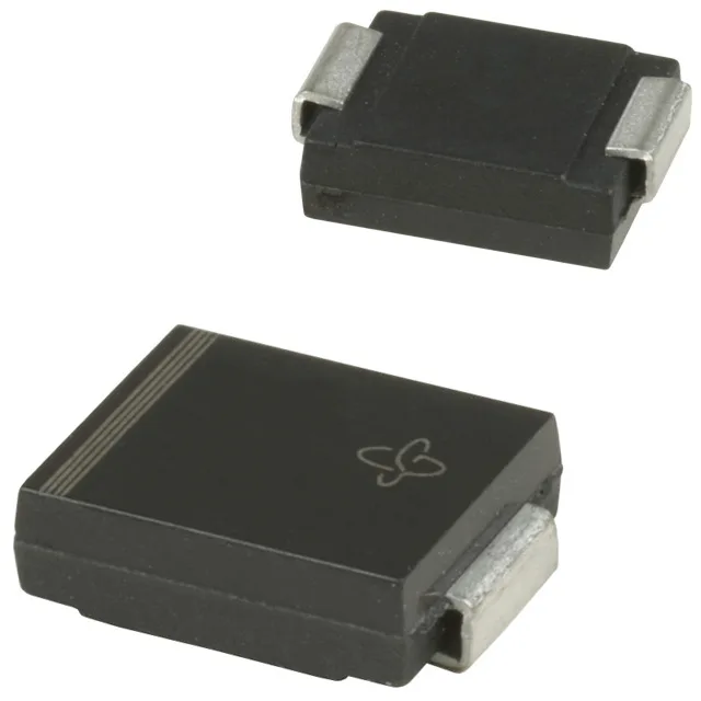
1500W peak pulse in a DO-214AB footprint
The 1.5SMC130A-E3/57T: That 1500W rating means it can absorb a surge of 8.4A peak pulse current and clamp it to 179V maximum, protecting downstream circuitry from transients on a 111V nominal rail. For a 100V DC bus or a 120V AC rectified rail, this part sits just above the operating voltage, so it stays invisible until a surge hits.
Clamping voltage and surge current limits
At the 8.4A peak pulse current (10/1000µs test waveform), the clamping voltage is 179V maximum. The 1500W peak pulse power is the product of clamp voltage and pulse current; it sets the energy-handling capacity for a single transient event. The junction temperature range spans -65°C to 150°C, which covers both cold-start conditions in outdoor equipment and self-heating during repetitive surge events.
Package and board integration
The SMC footprint is larger than the smaller SMA/SMB packages, which helps dissipate the 1500W pulse into the PCB copper — the thermal pad under the cathode tab should connect to a ground plane pour to keep the junction temperature rise within the 150°C limit during repetitive surges. The single unidirectional channel means the cathode band marks the protected side; the anode connects to ground. For bipolar or AC signal lines, two devices back-to-back or a bidirectional TVS would be needed — this part is for positive-rail clamping only.