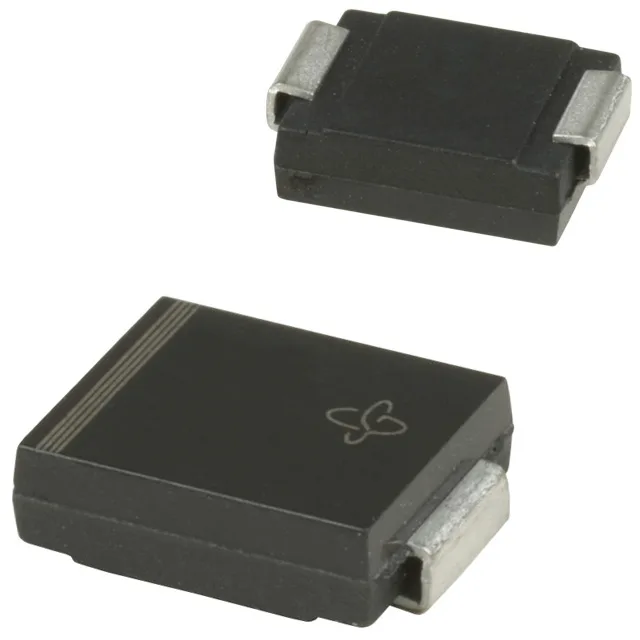
1500 W peak pulse — the surge rating that decides the protection envelope
The 1.5SMC100A-M3/57T: That 1.5 kW rating means it can clamp a transient that would otherwise exceed the breakdown voltage of the downstream silicon — a 24 V or 48 V DC bus with a 85.5 V standoff leaves margin for nominal rail ripple while catching surges up to 137 V. The unidirectional channel (single diode) clamps positive transients above the breakdown threshold; for AC or bidirectional protection you would need two devices or the bidirectional variant. The 10.9 A peak pulse current at the 10/1000 µs test condition confirms the diode can handle the full 1500 W without exceeding the clamping voltage.
Breakdown and clamping window — where the protection sits
Reverse standoff voltage is 85.5 V — the diode does not conduct below that, so it stays invisible to the protected rail during normal operation. Breakdown starts at 95 V minimum, and the clamping voltage at peak pulse current is 137 V maximum. That 42 V window between standoff and clamp is the voltage excursion the load must survive; a 100 V-rated MOSFET on the rail has margin. Operating temperature spans -65°C to 150°C (junction), which covers cold-start in outdoor telecom cabinets and the self-heating from repetitive surges. The DO-214AB (SMC) package with a copper pad area under the cathode tab sets the thermal resistance; the 1500 W rating assumes the board layout follows the recommended land pattern.
Active production — no end-of-life watch needed
The base product number is 1.5SMC100; the -M3/57T suffix denotes the packaging (Tape & Reel) and the Vishay Green/ RoHS-compliant plating.