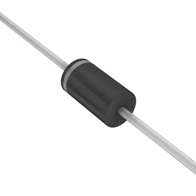
The 1.5KE91AHE3_A/C: This is a 1.5 kW peak-pulse TVS in the TransZorb series, rated for a 10/1000 µs waveform. The 86.5 V minimum breakdown and 125 V clamp mean it triggers well above a 24 V nominal rail's worst-case load-dump transient, but still catches the surge before it reaches downstream silicon. The 77.8 V reverse standoff is the DC operating ceiling — the diode stays off below that voltage, so it doesn't leak onto a 48 V bus. Peak pulse current is 12 A at the clamp voltage. For a 12 V system, the margin between the 77.8 V standoff and the clamp is wide enough that a 24 V supply rail won't false-trigger on normal switching noise.
AEC-Q101 and the under-hood temperature envelope
The -55 to +175 °C junction range covers engine-bay ambient and self-heating during a pulse — the 175 °C ceiling is the die's limit, not the solder joint's. The TransZorb series uses a glass-passivated junction that holds leakage stable across the temperature range. On a bench, you'll see the leakage climb above 125 °C, but the passivation keeps it from thermal runaway under repetitive pulses.
DO-201AA (DO-27) axial leaded package — through-hole mount with a 0.042-inch lead diameter. The body is 9.1 mm long; the anode band is the cathode end. For rework, the axial leads need a 1.2 mm hole in the PCB; a standard soldering iron with a 2 mm chisel tip wets the joint in 2-3 seconds. No moisture sensitivity level to track — the glass passivation doesn't absorb humidity. Tape-and-reel packaging is the factory format — the axial leads are taped between carrier tapes with a 0.75-inch pitch. For a repair bench, you'll likely see the loose part in a cut tape or a bulk bag; the cathode band is the only orientation mark.