Transient suppression for 64 V rails
The 1.5KE75A-E3/54: With a 64.1 V reverse standoff voltage, it sits on a nominal 48 V to 60 V DC bus — common in telecom rectifiers, industrial power supplies, and battery-backed systems — and clamps transients to 104 V maximum at the 14.6 A peak pulse current. The 71.3 V minimum breakdown voltage gives a 7.2 V margin above the standoff level before the diode starts conducting, so normal line ripple and load transients below that threshold leave the circuit undisturbed.
Clamping voltage and pulse current — the real stress limits
At the 14.6 A peak pulse current (10/1000 µs), the clamping voltage holds at 104 V maximum. That 104 V is the voltage the protected downstream components must survive — a 100 V-rated MOSFET on the same rail has no margin; a 150 V-rated part does. The 1500 W rating is the product of clamp voltage and peak current at that waveform, so a shorter pulse (8/20 µs) allows higher peak current before the junction temperature limit is reached.
Through-hole axial package for manual or wave-solder assembly
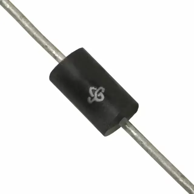
Housed in a DO-201AA (DO-27) axial-lead package, the 1.5KE75A-/54 mounts through-hole on the PCB. The lead spacing and body diameter match standard 0.100-inch pitch layouts, and the axial format allows either vertical or horizontal mounting for tight board profiles. Supplied in tape-and-reel (TR) or cut-tape (CT) quantities, the TR option suits automated insertion lines; the CT works for prototype or low-volume builds. The base product number 1.5KE75 covers the full family variants — the A suffix denotes 5% tolerance on breakdown voltage.
Active production — no last-time-buy pressure
Because it is a general-purpose TVS diode (not a power-line protector), it is suited for signal and DC rail clamping in industrial, telecom, and automotive auxiliary circuits where the 64.1 V standoff matches the operating voltage.