Clamping performance and protection window
The 1.5KE56CA-E3/54: Its breakdown voltage range starts at 53.2V minimum, clamping at 77V maximum under a 19.5A peak pulse current (10/1000µs waveform). This window means a 48V bus sees the TVS remain transparent during normal operation but begin conducting before the rail exceeds the downstream device's absolute maximum rating.
Rated for continuous junction temperatures from -55°C to 175°C, this part suits environments where the ambient spans outdoor telecom cabinets, engine compartments, or industrial control enclosures. The 1500W peak pulse rating is derated above 25°C per the standard TransZorb derating curve; at 175°C the peak pulse power drops to approximately 150W, so the thermal margin at the operating temperature must be checked against the expected surge energy.
Package and board integration
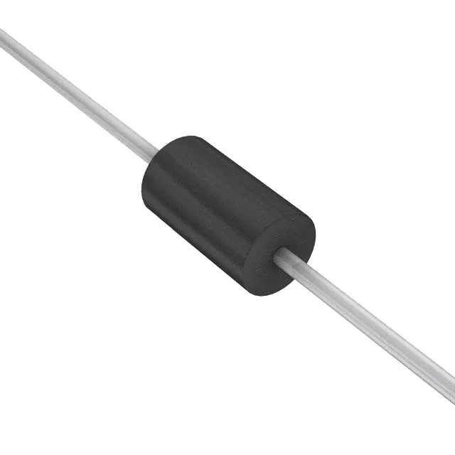
Housed in a DO-201AA (DO-27) axial leaded package, the 1.5KE56CA-/54 mounts through-hole on the PCB. The axial body allows either vertical or horizontal placement; for high-surge applications, the lead length between the TVS and the protected rail should be kept under 10 mm to minimise inductive voltage drop that reduces clamping effectiveness at the load.