Clamping voltage and pulse current — the fit decision
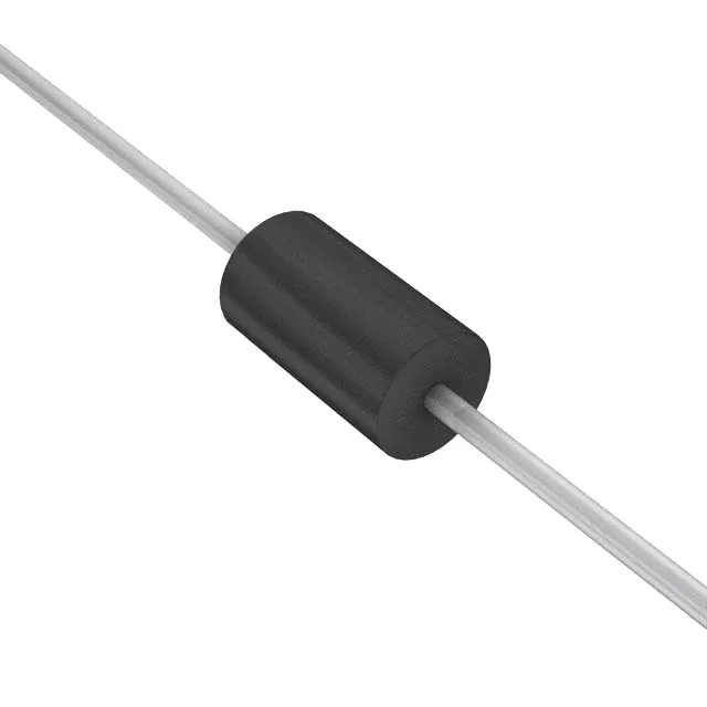
The 1.5KE20CA-E3/51: When a transient hits, the diode clamps at 27.7 V maximum while conducting 54.2 A peak pulse current (10/1000 µs). That clamping ceiling tells you the downstream silicon must survive 27.7 V without avalanche breakdown — a 30 V-rated MOSFET has 2.3 V of headroom; a 24 V-rated part does not. The bidirectional configuration (single die, symmetrical breakdown) means it clamps equally on positive and negative transients — useful on AC signal lines or DC rails where reverse polarity is a risk. No power-line protection feature is built in, so this is a signal-rail or low-power bus protector, not a mains-side suppressor. The axial DO-201AA body handles the 1.5 kW pulse without cracking the epoxy encapsulation, but the lead length and PCB copper area set the steady-state thermal resistance.
Through-hole DO-201AA (also known as DO-27) axial leads — the body diameter is about 5.3 mm, lead diameter 1.3 mm. The hole diameter on the PCB should be 1.0–1.1 mm for a solid solder fillet; lead spacing is non-standard, so bend the leads to fit a 0.4-inch or 10 mm pitch on the board. Supplied in bulk (/51 suffix indicates bulk packaging, 51 pieces per bag). No tape-and-reel option; hand-insertion or tube-fed wave-solder only.