Protection window and pulse capability
The 1.5KE20A/54: The reverse standoff voltage of 17.1 V means the device remains non-conductive below that rail — it only begins to avalanche when the transient exceeds the minimum breakdown voltage of 19 V. This 17.1 V standoff makes the part suitable for protecting 12 V or 15 V DC rails where the nominal supply stays below the standoff threshold, but a transient spike up to 27.7 V is clamped before reaching downstream silicon. The 1500 W rating at the 10/1000 µs pulse defines the energy-handling ceiling — shorter pulses (8/20 µs) allow higher peak current, but the datasheet's derating curve governs the actual safe operating area at elevated ambient temperatures.
Package and deployment context
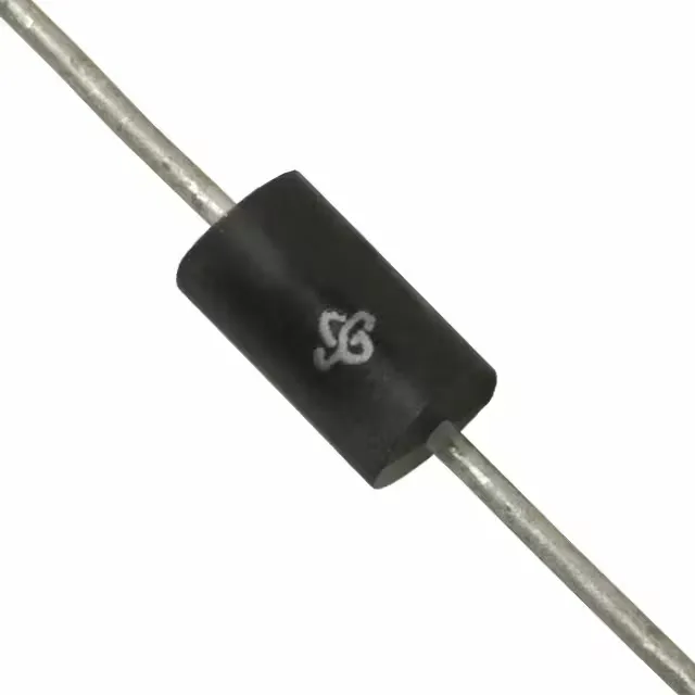
Housed in a DO-201AA / DO-27 axial-lead through-hole package, the 1.5KE20A/54 mounts into boards that already carry a hole pattern for this footprint — common in legacy power supplies, industrial control boards, and telecom line cards where the axial body is wave-soldered or hand-soldered into plated through-holes. The wide junction temperature margin also matters for derating the peak pulse power at high ambient — a 1500 W rating at 25 °C drops to roughly 50 % at 175 °C, per the standard TVS derating curve.
Sourcing reality for an obsolete TVS
Because the part is obsolete, a buyer evaluating a new design should select an active TVS with a matching standoff voltage (17.1 V) and comparable clamping performance.