Clamping a 15.3V rail with 1500W headroom
The 1.5KE18CA-E3/54: Its 15.3V reverse standoff voltage (V_RWM) means it sits across a 12V or 15V DC bus without conducting leakage; the breakdown window starts at 17.1V min and the clamping voltage is capped at 25.2V at the full 59.5A peak pulse current. This voltage stack is designed for protecting sensitive downstream silicon from inductive load dumps, lightning-induced surges, and ESD transients on a nominal 12V or 15V supply rail.
Package and thermal reality for the axial leaded form
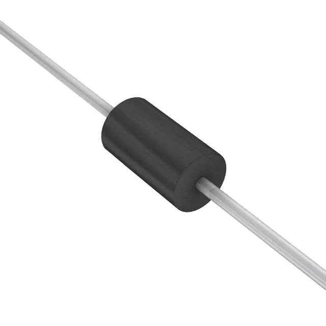
Housed in the DO-201AA (DO-27) axial leaded package, this through-hole part is intended for point-to-point wiring or PCB mounting with the leads forming the primary thermal path. The junction temperature range spans -55°C to 175°C, which is the full military-grade band — the device dissipates transient energy into the lead wires and the copper pad area on the board, not through a separate tab. The 1500W rating assumes the leads are soldered into a 10×10 mm copper pad per the datasheet's mounting condition; a smaller pad or free-air wiring derates the peak pulse capability.