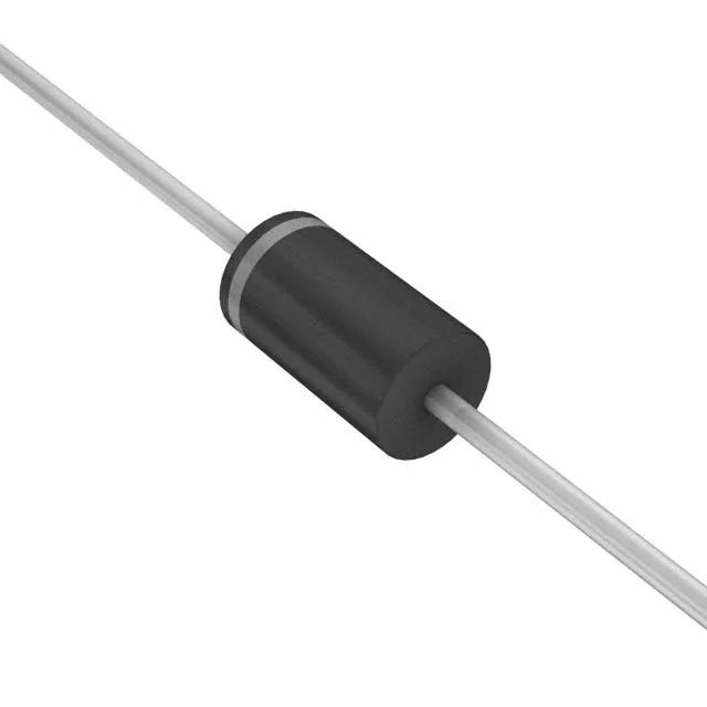
The 1.5KE13-E3/73: Its 10.5V reverse standoff voltage means it sits across a nominal 12V bus and stays transparent until a transient pushes the line above 11.7V (minimum breakdown), at which point it clamps at 19V maximum while shunting up to 78.9A peak current — a protection window sized for 12V battery systems and unregulated supplies.
For a BOM that already carries this part number, the only sourcing path is through independent distribution channels that hold new-old-stock or surplus inventory. Each lot is verified for authenticity and date code, and availability is confirmed at the time of quote — no standing stock is assumed. If your design is still in development, the practical move is to qualify a current-production TVS with the same 10.5V standoff and 1500W rating in a DO-201 package — several manufacturers offer pin-compatible alternatives that drop into the same axial footprint without a board spin.
Key ratings that decide the fit
For a 12V rail, the 78.9A peak current at 19V clamping means it handles a direct lightning-induced surge at the secondary side of a telecom rectifier, but not a primary AC mains hit (the device has no power line protection rating). The 10.5V reverse standoff (working voltage) is the DC bias the diode sees continuously — it must be above the nominal rail voltage to avoid self-heating. The 11.7V minimum breakdown gives a 1.2V guard band before clamping starts, which is tight enough for a regulated 12V supply but marginal for a battery floating at 13.8V under charge. Single unidirectional channel means the cathode band must face the positive rail — reverse polarity installation leaves the line unprotected and the diode forward-biased, which will short the supply.