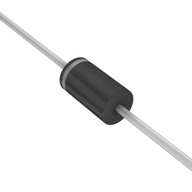
1.5kW bidirectional transient suppressor — 81 V standoff, 144 V clamp
The 1.5KE100C-E3/54: With an 81 V reverse standoff voltage and a 144 V maximum clamping point at 10.4 A peak pulse current, this part clamps transients on 48 V to 72 V DC rails — common in telecom rectifiers, industrial DC buses, and battery-backed supplies. The bidirectional configuration (single die, symmetrical breakdown) means polarity is irrelevant; it clamps equally on positive or negative swings, which simplifies layout on AC-coupled or floating rails where the ground reference is not guaranteed.
Breakdown and clamping — what the ratings mean for the rail
The minimum breakdown voltage is 90 V; the standoff (working voltage) is 81 V. A rail running at 72 V nominal stays below the standoff, so the diode sees only leakage current. When a surge drives the rail above 90 V, the avalanche region engages, and the voltage is clamped at 144 V maximum — this is the voltage the downstream components see during the pulse. The 10.4 A peak pulse current rating at the 10/1000 µs waveform defines the surge-handling capability. For shorter pulses (8/20 µs, common in ESD or lightning tests), the peak current capability is higher — the 1500 W figure is the energy envelope the die absorbs without failure. At high ambient temperature the power derating curve (not captured here) reduces the allowable peak pulse power — a 125°C ambient roughly halves the 1500 W rating.
Through-hole axial DO-201AA — board-fit and replacement note
The DO-201AA (DO-27) axial-lead package fits standard 0.100-inch (2.54 mm) pitch through-hole pads. The body length is about 9.1 mm; lead diameter is 1.3 mm. For replacement in an existing board, the hole diameter should accommodate the lead without forcing — 1.5 mm minimum finished hole size is typical. The tape-and-reel packaging (/54 suffix) indicates it ships on a 13-inch reel with 54 mm tape width, suitable for auto-insertion equipment. For hand-prototype or low-volume repair, the same die is also available in bulk or ammo-pack under alternate order codes.
Obsolete — sourcing through independent channels
Vishay has marked the 1.5KE100C-/54 as obsolete. No direct factory second-source is listed. For a BOM that already uses this order code, the DO-201AA footprint is shared by the entire 1.5KE series (P4KE, SA, P6KE families also fit the same hole pattern), so a parametric replacement with a different Vishay or Littelfuse bidirectional TVS at the same standoff voltage is a board-compatible option if the original is unavailable.