1500 W peak pulse — the clamp that defines the guard band
The 1.5KE100-E3/54: The 144 V clamping voltage at 10.4 A peak pulse current (10/1000 µs waveform) sets the upper limit the downstream circuitry must survive — anything below that clamp voltage is protected. Breakdown starts at a minimum of 90 V, so a nominal 81 V supply has 9 V of headroom before the diode begins conducting leakage current. That guard band keeps the TVS out of the circuit during normal operation while still catching a transient before it reaches the load.
Obsolete — sourcing through independent channels
Vishay lists the 1.5KE100-/54 as obsolete. The DO-201AA axial package and through-hole mounting mean a board spin is required to adopt a surface-mount alternative. If the design is still in prototype phase, a parametric search on 81 V standoff and 1500 W peak pulse in a through-hole package is the starting point for a replacement qualification.
Temperature range and package — the deployment envelope
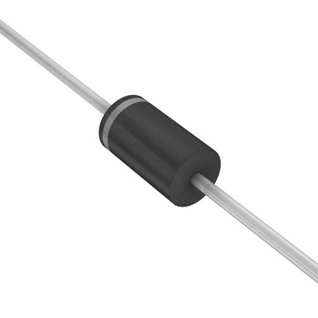
The DO-201AA axial body handles the thermal pulse of a 1500 W, 10/1000 µs surge without secondary breakdown — the leaded package conducts heat into the PCB traces and surrounding copper area. No power line protection (the device is unidirectional, single-channel), so it is intended for signal or DC bus clamping, not AC mains. The single unidirectional channel means polarity matters — install with the cathode toward the protected rail.