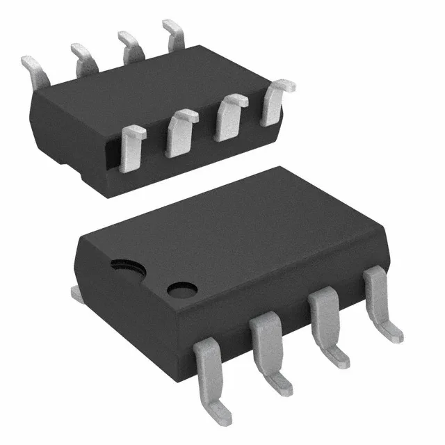
TLP352(TP1,F)

Toshiba Semiconductor

Toshiba TLP352(TP1,F) optical coupling gate driver, 1-channel, 3750Vrms isolation, 2.5A peak output, 15ns/8ns rise/fall, 8-SMD gull wing package, -40°C to 125°C, Active.

Toshiba Semiconductor TLP352(TP1,F)
Download datasheet (PDF)
[IN STOCK] In Stock: 15,985 pcs
$1.33/ pc

Volume pricing

Buy Now

MOQ 1 · Tape & Reel (TR); Cut Tape (CT) · RoHS · EIA-481 · DAP/DDP · T/T

Technical specifications

TLP352(TP1,F) specifications
Parameter / AttributeSpecification / Value
MountingSurface Mount
Voltage - isolation3750Vrms
Voltage - output supply15V ~ 30V
Voltage - forward (Vf)1.55V
Current - peak output2.5A
Current - output high, low2A, 2A
Current - DC forward (If)20 mA
Operating temperature-40°C ~ 125°C
Pulse width distortion50ns
Approval agencyCSA, cUL, UL
PackageTape & Reel (TR); Cut Tape (CT)
TechnologyOptical Coupling
Case8-SMD, Gull Wing
Channels1
Rise (Fall time)15ns, 8ns
Propagation delay tpLH (tpHL)200ns, 200ns
Common mode transient immunity20kV/µs
100% Footprint Match · Solder-Ready (No PCB Redesign Needed)

Need Stock or a Drop-in Second-Source for TLP352(TP1,F)?

Package: DIP-8 (gate-drive optocoupler) · Pin-compatible replacements with immediate Shenzhen spot stock

Footprint Match 97%
Supply Chain & Allocation Reality:

This eight-pin row is how inverter, servo and welder drive boards cross the isolation barrier to fire their IGBTs: TLP250 from Toshiba, HCPL-3120/A3120 from the Avago lineage, FOD3120 from the Fairchild line - four houses, one socket, and a repair literature that swaps them by name. The selection axis is output current (TLP250 at a 1.5A peak against the 2.5A class of its successors) and input threshold (the 3120 triggers from a lower LED current), and the design axis is the negative gate rail that keeps Miller capacitance from re-triggering the IGBT. In repair, the row behaves; what re-fails is the rail and the bypass capacitor the procedure keeps forgetting.

Verified Pin-Compatible Replacements (3 verified alternatives)

TLP350 Toshiba DIP-8
100% Drop-in (Zero Code Change)
Availability & Target Pricing:

The Documented Upgrade in the Same Socket

Shenzhen Spot Stock (24-48h Dispatch)

Electrical & Core Specs:

The higher-output member: about +/-2.5A peak against the TLP250s +/-1.5A, aimed at 1200V IGBTs in the 20-100A class, with lower supply current - the direct upgrade path of the row.

Gate-side supply in the 10-35V class; isolation 2500V class.

Compatibility & Drop-In Notes: The substitution rule reported from inverter repair: in low-power drives the smaller part can stand in for the bigger; in mid and high-power drives the output current difference matters, although many designs carry a post-amplifier stage that softens it.
Package & Solder Footprint: Standard 8-pin gate-drive optocoupler pinout across the row.
Shenzhen Warehouse Stock & MOQ: Active Toshiba line; the forward part of the socket.
HCPL-3120 Broadcom (Avago) DIP-8
Functional Equivalent
Availability & Target Pricing:

The Other House of the Same Socket

Shenzhen Spot Stock (24-48h Dispatch)

Electrical & Core Specs:

The Avago-line drive optocoupler: about +/-2A output, direct drive of 150A/1200V IGBT modules, and a lower LED threshold (about 2.5mA) that changes the input-side resistor arithmetic.

15V to 30V gate-side supply; isolation 1414V class (the HCNW variant carries the higher figure).

Compatibility & Drop-In Notes: The input-current difference is the practical one when crossing houses: a drive resistor sized for the 250s 5mA can overdrive a 3120s LED budget - and the reverse starves. Recompute the input resistor, then treat the row as interchangeable.
Package & Solder Footprint: Same 8-pin socket; the HCNW3120 is electrically the same part in a wider isolation body.
Shenzhen Warehouse Stock & MOQ: Multi-line stock; the standard alternative of the drive-repair trade.
FOD3120 onsemi (Fairchild line) DIP-8
100% Drop-in (Zero Code Change)
Availability & Target Pricing:

The Fairchild-Line Member

Shenzhen Spot Stock (24-48h Dispatch)

Electrical & Core Specs:

The Fairchild-line drive optocoupler with the 2.5A-class output: functionally the TLP350 of the row in the onsemi lineage.

Same gate-side envelope as the row.

Compatibility & Drop-In Notes: The row rule applies: verify the input threshold figure of the exact member, recompute the LED resistor if crossing houses, and treat output current as the power-class decision.
Package & Solder Footprint: Standard 8-pin pinout.
Shenzhen Warehouse Stock & MOQ: Stocked with the row; the documented second source for A3120 designs.
Buyer & Quality Checklist for Sourcing Alternatives
  • The negative gate rail is the design, not the luxury: a VEE below emitter (the +15/-15V or +15/-8V schemes) prevents Miller-capacitance false turn-on in bridge drives. Repairs that skip the negative rail reintroduce the shoot-through the original design existed to avoid.
  • The bypass capacitor lives between pins 8 and 5 (0.1uF class) - it is in every application note and on no repair checklist; missing it turns switching transients into mysterious drive glitches.
  • Crossing houses recomputes the input resistor: Toshiba members trigger around 5mA, the 3120 family around 2.5mA - the difference is the LED and eventually the driver behind it.
  • Output current is the power-class axis: 1.5A against 2.5A peaks decides whether the part drives the IGBT gate directly or leans on a post-amplifier stage - read the schematic, not the name.
  • When a drive optocoupler fails, the IGBT usually failed first (or together): meter the gate-emitter junction and the collector path before fitting the third driver into the same board.
  • In repair inventory, the row is one drawer with one trap: isolation grade differences (HCNW and wide-body variants) mean the subs that exist on paper are not always subs on the board.
Frequently Asked Technical Questions

Q: Can TLP250 and HCPL-3120 replace each other?

A: In low-power drives yes - the reported practice is direct interchange in the 8-pin socket - with the input-resistor recomputation for the different LED thresholds (about 5mA against 2.5mA). In mid and high-power drives compare the output-current class first.

Q: What drives TLP250 output current selection?

A: The IGBT gate charge and the absence of a post-amplifier stage: 1.5A peaks suit the 50A/1200V class the TLP250 was specified for, while the 2.5A members (TLP350, FOD3120) cover 20-100A modules without help.

Q: Why do repaired inverter drives fail again at power-up?

A: Commonly the negative gate rail or the missing bypass capacitor: without VEE the Miller capacitance false-triggers the bridge, and without the 0.1uF at pins 8-5 the drive sees every switching transient. Check both before blaming the new optocoupler.

Technical details

Optical coupling gate driver for IGBT and MOSFET switching

The Toshiba TLP352(TP1,F) is a single-channel optical coupling gate driver delivering a 2.5A peak output current with 3750Vrms isolation between input and output. It comes in an 8-SMD gull wing package rated for surface-mount assembly. The part is designed for driving IGBTs and power MOSFETs in motor drives, inverters, and industrial power supplies where galvanic isolation is required between the control and power stages.

2.5A peak output — which gate it drives

The 2.5A peak output current is the headline rating that determines the gate charge it can source and sink per switching cycle. With 2A typical high and low output capability, this driver comfortably handles medium-power IGBTs and MOSFETs up to the 600V/30A class in hard-switching topologies. The 15ns rise and 8ns fall times keep switching losses low, but the 200ns maximum propagation delay means you budget that dead-time margin in the PWM timing.

3750Vrms isolation and 20kV/µs CMTI

The 3750Vrms isolation rating provides the reinforced insulation barrier typical for motor-drive and industrial power applications. The 20kV/µs minimum common-mode transient immunity ensures the output stays latched correctly when the power-stage switching edges couple fast dv/dt across the isolation gap — a critical parameter in inverter designs where the floating ground jumps several hundred volts in tens of nanoseconds.

Temperature range and supply voltage

The output supply range of 15V to 30V covers standard gate-drive rails for IGBTs and MOSFETs; the typical forward voltage of 1.55V and maximum 20 mA input LED current are compatible with 3.3V or 5V logic outputs through a current-limiting resistor.

It is RoHS compliant and approved by CSA, cUL, and UL, covering North American safety certification requirements for reinforced insulation in power equipment.

TLP352(TP1,F)
[ALLOC] verified
Quote