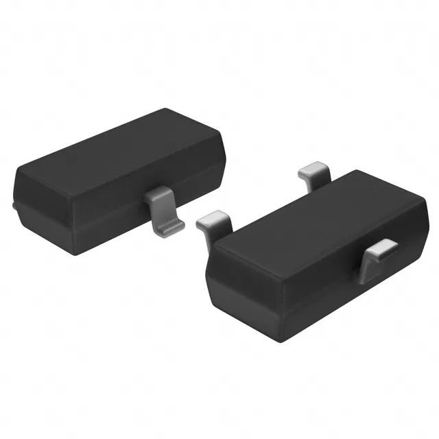
Toshiba Semiconductor RN1415,LF — Interface & Transceivers

RN1415,LF NPN Pre-Biased Transistor, 50 V, 100 mA, SOT-23-3

MPNRN1415,LF
End of Life

Toshiba RN1415,LF, NPN Pre-Biased, 50 V Vce, 100 mA Ic, 250 MHz ft, 200 mW, SOT-23-3, ROHS3.

$0.17Ref. price · indicative, final on quote
PackagingTO-236-3, SC-59, SOT-23-3
RoHSROHS3 Compliant
Sourced new & surplus through independent channelsAuthenticity-screened · ESD-safe packingListing updated Jul 2026

Specifications

RN1415,LF specifications
ParameterValue
MountingSurface Mount
FET typeNPN - Pre-Biased
Voltage - collector emitter breakdown50 V
Current - collector (Ic)100 mA
Current - collector cutoff500nA
DC current gain (hFE) (Min) @ ic, vce50 @ 10mA, 5V
Power - max200 mW
Frequency250 MHz
PackageTape & Reel (TR); Cut Tape (CT)
CaseTO-236-3, SC-59, SOT-23-3
Resistor - base (R1)2.2 kOhms
Resistor - emitter base (R2)10 kOhms
Vce saturation (Max) @ ib, ic300mV @ 250µA, 5mA

Product details

Built-in bias resistors shrink the BOM

The RN1415,LF is a Toshiba NPN pre-biased transistor that integrates a 2.2 kΩ base resistor (R1) and a 10 kΩ base-emitter resistor (R2) inside the package. That means you skip two external passives and the associated PCB real estate — a clean fit for dense boards where every 0402 counts.

Maximum power dissipation is 200 mW, which limits continuous collector current depending on the Vce drop. At 5 mA Ic and 300 mV Vce(sat) (the rated saturation condition at 250 µA base drive), dissipation is roughly 1.5 mW — well within margin. If you push closer to 100 mA continuous at higher Vce, the thermal budget fills fast; the SOT-23-3 package has modest copper area for heat spreading. Keep the ambient below 85 °C for sustained high-current duty, or derate accordingly.

No last-time-buy or discontinuation notice is in effect. If you need a second-source option, the RN1417(TE85L,F) is a functional peer with different internal resistor values (10 kΩ base, 4.7 kΩ base-emitter) — verify the bias network matches your drive conditions before substituting.

Frequently asked questions

What are the resistor values inside RN1415 LF?

The internal base resistor (R1) is 2.2 kΩ, and the base-emitter resistor (R2) is 10 kΩ. These values set the turn-on threshold and base current for a given input voltage.

What is the closest functional second-source for RN1415 LF?

The RN1417(TE85L,F) is a functional peer with the same 50 V, 100 mA, 250 MHz ratings and SOT-23-3 package, but its internal resistors differ: R1 = 10 kΩ, R2 = 4.7 kΩ.