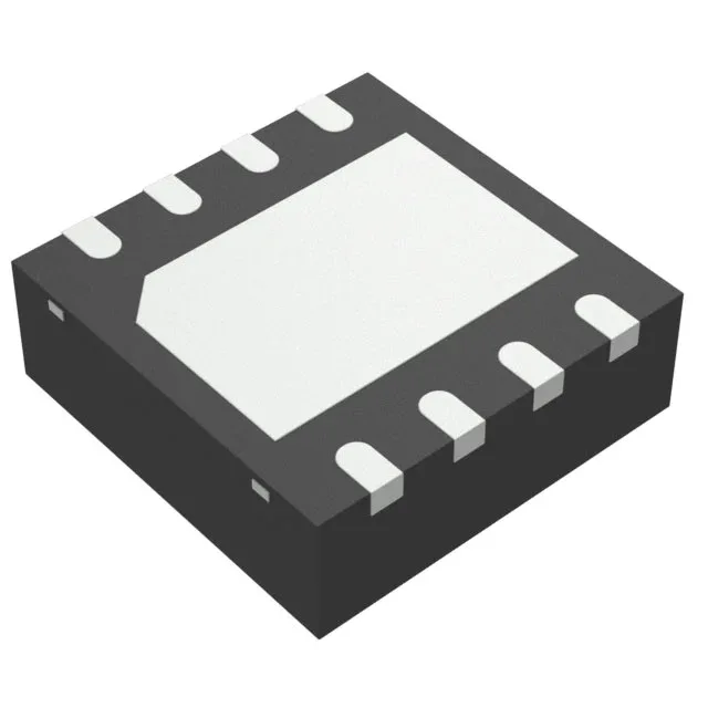
UCC27201ADRMR

Texas Instruments

Texas Instruments UCC27201ADRMR, half-bridge gate driver, N-channel MOSFET, 3A peak source/sink, 8V~17V supply, 120V bootstrap max, 8-VSON exposed pad package, -40°C~140°C junction range

Texas Instruments UCC27201ADRMR
Download datasheet (PDF)
[IN STOCK] In Stock: 1 pcs
$5.62/ pc

Volume pricing

Buy Now

MOQ 1 · Tape & Reel (TR); Cut Tape (CT) · RoHS · EIA-481 · DAP/DDP · T/T

Technical specifications

UCC27201ADRMR specifications
Parameter / AttributeSpecification / Value
Gate typeN-Channel MOSFET
Input typeNon-Inverting
Channel typeIndependent
MountingSurface Mount
Supply voltage8V ~ 17V
Logic voltage - VIL, VIH0.8V, 2.5V
High side voltage - max (Bootstrap)120 V
Current - peak output (Source, sink)3A, 3A
Operating temperature-40°C~140°C(TJ)
PackageTape & Reel (TR); Cut Tape (CT)
Case8-VDFN Exposed Pad
Number of drivers2
Driven configurationHalf-Bridge
Rise (Fall time)8ns, 7ns

Technical details

Half-bridge driver for N-channel MOSFETs

It delivers 3A peak source and 3A peak sink current, which means it can charge and discharge the gate capacitance of large power FETs quickly — expect clean switching up to several hundred kilohertz in a typical motor drive or DC-DC converter. The bootstrap high-side voltage is rated to 120 V maximum. The supply range is 8 V to 17 V. Rise and fall times are 8 ns and 7 ns typical — fast enough to minimise cross-conduction losses, but the PCB layout must keep the gate loop inductance low to avoid ringing. The non-inverting input means a logic-high on the input turns the corresponding output on; no inversion to confuse the firmware.

The supplier device package is 8-VSON (4x4).

Orders are placed against standard lead times; no special LTB planning required for this BOM line. ROHS3 compliant.

UCC27201ADRMR
[ALLOC] verified
Quote