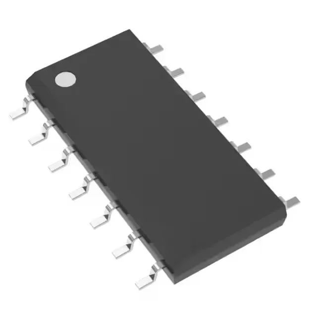
What the 96% duty cycle means for your transformer design
The UC3842ADTR is a current-mode PWM controller from Texas Instruments that drives a single transistor output at a maximum duty cycle of 96%. That near-unity duty cycle is the headline parameter for flyback and forward converters: it allows the primary switch to stay on for almost the entire switching period, which directly sets the minimum off-time available for transformer core reset. In a forward converter, a 96% duty cycle forces a reset winding or active clamp to complete the reset in the remaining 4% — a design constraint that drives the turns ratio and the clamp voltage stress on the switch.
Switching frequency ceiling and gate-drive budget
The controller oscillates up to 500 kHz. At the upper end of that range, the gate-drive current drawn from the Vcc rail (10 V–30 V,) becomes a significant fraction of the bias supply budget — a 1 nF gate capacitance switched at 500 kHz draws roughly 0.5 mA from the driver, which the UC3842ADTR's totem-pole output can handle, but the designer must account for it in the auxiliary winding regulation. The 500 kHz ceiling also shrinks the transformer core cross-section, which is the usual reason to push frequency higher in a compact supply.
Temperature grade and commercial deployment boundary
That commercial temperature range fits indoor power supplies, office equipment, and appliance PSUs, but it excludes outdoor telecom cabinets, engine-bay converters, and any environment where the ambient can dip below freezing or rise above 70°C. For those applications, the industrial-grade UC3842A (or the automotive AEC-Q100 LM5150QURUMRQ1,) extends the temperature range to -40°C or higher.
Package and supply rail fit
The 10 V–30 V supply range means the controller can be biased directly from a rectified 24 V AC auxiliary winding or a 12 V–15 V regulated rail, but it cannot run from a 5 V-only bias — a 12 V rail is the practical minimum. The single transistor-driver output drives an external MOSFET or BJT; there is no synchronous rectifier output, so the secondary-side rectifier must be a diode or a separate SR controller.