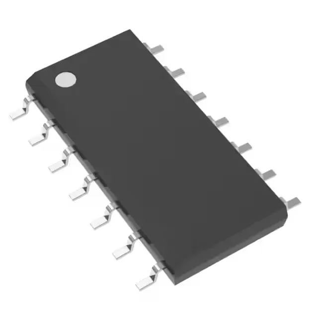
Texas Instruments UC3842ADG4 — Power Management (PMIC / Gate Driver)

UC3842ADG4 PWM Controller, 500 kHz, 96% Duty Cycle, Active

MPNUC3842ADG4
End of Life

Texas Instruments UC3842ADG4 current-mode PWM controller, 14-SOIC, 10V-30V supply, up to 500 kHz switching, 96% max duty cycle, 0°C to 70°C.

Independent supplier — new & surplus stockAuthenticity-screened · ESD-safe packingListing updated Jul 2026

Specifications

UC3842ADG4 specifications
ParameterValue
Output typeTransistor Driver
MountingSurface Mount
Voltage - supply (Vcc (Vdd))10V ~ 30V
Frequency - switchingUp to 500kHz
I/O channels1
Output phases1
Duty cycle96%
Operating temperature0°C~70°C(TA)
PackageTube
FunctionStep-Up, Step-Down, Step-Up/Step-Down
TopologyBoost, Buck, Flyback, Forward
Clock syncNo
Case14-SOIC (0.154\", 3.90mm Width)
Control featuresFrequency Control
Output configurationPositive, Isolation Capable
Synchronous rectifierNo

Product details

500 kHz switching ceiling and 96% duty cycle

Switching frequency goes up to 500 kHz, which lets you shrink the transformer or inductor core size compared to a 100 kHz design — the trade-off is higher switching losses in the MOSFET and snubber components. The 96% maximum duty cycle gives headroom for low-dropout operation in a buck converter or wide input-range flyback; at 96 % the off-time is only 4 % of the period, so the transformer reset voltage needs careful design.

Topology flexibility: boost, buck, flyback, forward

This current-mode controller supports step-up, step-down, and step-up/step-down topologies — boost, buck, flyback, and forward converters are all on the table. The single output drives an external MOSFET via a transistor driver stage; the control loop uses frequency compensation through the COMP pin, and the part includes frequency control (oscillator timing via Rt/Ct).

Vcc supply range is 10 V to 30 V, which covers standard bias rails from 12 V to 24 V industrial supplies. No synchronous rectifier option; the output is a single transistor driver, not a totem-pole pair.

14-SOIC package — rework-friendly footprint

Housed in a 14-SOIC (0.154-inch width, 3.90 mm body), surface-mount package. The 1.27 mm pitch is easy to hand-solder and inspect under a microscope; no thermal pad underneath, so the power dissipation path is through the leads and copper plane. Ships in Tube form.

Frequently asked questions

What is the maximum duty cycle of UC3842ADG4?

The maximum duty cycle is 96 %, which allows the controller to stay on for nearly the whole switching period — useful for low-dropout buck or wide-input flyback designs where the off-time is short.

Is UC3842ADG4 obsolete or active?

New designs can proceed without LTB risk.

What topology can UC3842ADG4 be used in?

It supports boost, buck, flyback, and forward topologies — step-up, step-down, and step-up/step-down configurations are all within its capability.

What is the difference between UC3842ADG4 and UC3842?

The UC3842ADG4 is the surface-mount 14-SOIC variant of the base UC3842 (which is typically available in DIP-8 or SOIC-8). The 'DG4' suffix indicates the SOIC-14 package and a specific lead-free / RoHS-compliant finish. Functionally they share the same current-mode PWM control core, but the pinout differs — the 14-SOIC version has additional NC pins and a different pin arrangement, so they are not drop-in replacements without a PCB layout change.