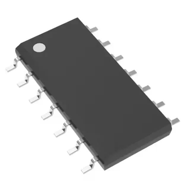
Switching frequency and duty-cycle limits for transformer design
The UC2844ADTR switches at up to 500 kHz, which sets the practical upper bound for transformer core size and turns ratio in a flyback or forward converter — a 100 kHz design leaves plenty of headroom, but pushing toward 500 kHz demands a core material with low loss at that frequency and careful layout to keep switching-node ringing within the 48% max duty-cycle window. The 48% duty-cycle ceiling means the controller cannot command on-times longer than 48% of the switching period — for a flyback operating in continuous conduction mode, this limits the maximum step-up ratio; if the design needs a higher ratio, the transformer turns ratio or the input voltage must compensate.
Multi-topology flexibility and external switch requirement
This part supports boost, buck, flyback, and forward topologies — the same controller can serve isolated and non-isolated rails across a BOM, reducing qualification effort. The output is a transistor driver, so an external power switch (MOSFET or BJT) is required; the controller does not integrate the switch, which gives the designer freedom to size the FET for the actual load current. The supply range spans 10 V to 30 V on Vcc, covering standard bias rails from a 12 V auxiliary winding or a 24 V industrial bus. The undervoltage lockout thresholds are set internally for this range, so no external UVLO resistor divider is needed.
Active lifecycle and compliance status
The part is ROHS3 compliant, which satisfies the material restriction requirements for EU and most global markets without an exemption expiry concern.