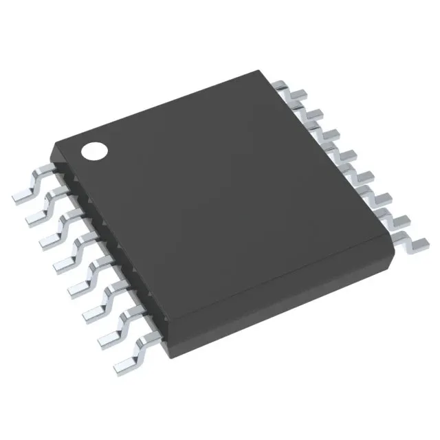
Quad SPDT switch in a 16-TSSOP footprint
The TS3A5018PWR is a Texas Instruments quad single-pole double-throw (SPDT) analog switch, integrating four 2:1 multiplexer/demultiplexer circuits in a single 16-TSSOP package. Each switch connects a common I/O to one of two independent signal paths, controlled by a logic-level select pin. With a 10 Ohm maximum on-resistance and 300 mOhm channel-to-channel matching, this part is sized for routing analog signals or digital data streams where insertion loss and gain flatness matter across the full 300 MHz -3dB bandwidth.
Signal integrity and switching speed
Crosstalk is specified at -48 dB at 10 MHz, meaning a signal on one channel couples into an adjacent off-channel at roughly 0.4% of its amplitude — low enough for 8- to 10-bit analog multiplexing in audio or instrumentation front-ends without noticeable bleed-through. Turn-on time is 8 ns maximum and turn-off is 6.5 ns maximum, giving a combined switching window under 15 ns. This timing margin supports multiplexing clock or data lines in the tens-of-MHz range without violating setup-and-hold at the downstream receiver. Charge injection is 2 pC typical — the amount of charge dumped onto the signal path when the switch opens. For a 10 kOhm source impedance driving a 10 pF load, that translates to roughly a 200 mV glitch, recoverable within a microsecond through the RC time constant.
Supply voltage and board integration
The switch's control logic thresholds track the supply, so no external level translation is needed when the select and enable pins are driven by the same rail as V+. The 0.173-inch width aligns with the narrow-body TSSOP land pattern; the exposed pad is absent on this variant, so thermal dissipation relies on the copper pour under the package and the board's internal planes. Operating temperature range is -40°C to 85°C, covering industrial and commercial environments. The leakage current is 100 nA maximum per channel in the off-state, which sets the floor for off-isolation at high source impedances — a 100 nA leak into a 1 MOhm load produces a 100 mV offset error.
Packaging options include Tape & Reel and Cut Tape, suiting both prototype builds and production reels.