Dual 3.5 A and 2.5 A rails from a single buck controller
The TPS65283-1RGET from Texas Instruments is a dual-channel synchronous step-down (buck) converter that delivers 3.5 A on one output and 2.5 A on the other, both adjustable down to 0.6 V. It takes an input from 4.5 V up to 18 V, which covers common 5 V, 9 V, 12 V, and 15 V supply rails without needing a pre-regulator. The two outputs share a single controller but switch independently, so you can power, say, a 3.3 V logic rail and a 1.8 V I/O rail from the same chip.
Switching frequency: inductor size vs. loss trade-off
At the low end you get better efficiency because switching losses drop, but the inductor needs to be physically larger to handle the ripple current. At 2 MHz the inductor shrinks — good for a tight layout — but the FET switching losses go up, and the thermal budget gets tighter. The synchronous rectifier helps keep those losses manageable across the band.
24-VQFN with exposed pad — the thermal path is your layout
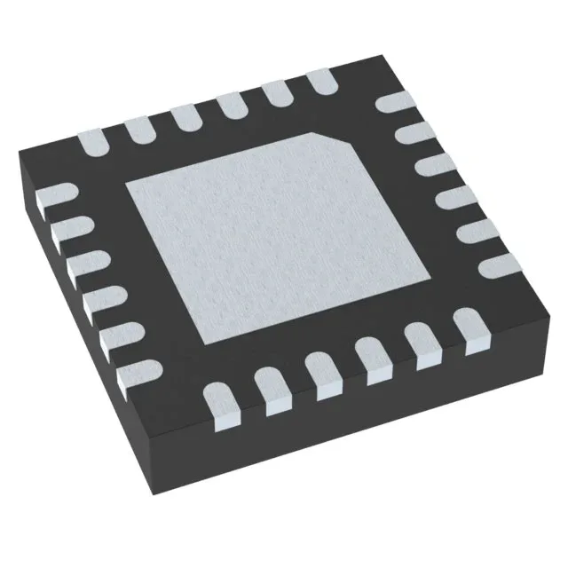
The part comes in a 24-VFQFN with exposed pad (4 mm × 4 mm body, 24-VQFN package code). That pad underneath is the main heat path out of the die. The PCB layout needs a matching copper land with thermal vias down to the ground plane — without them the junction temperature climbs fast, especially at the full 3.5 A + 2.5 A load.