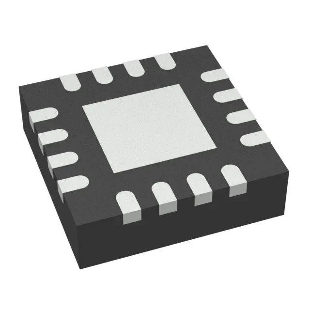
Texas Instruments TPS65135RTER — DC-DC Power Modules

TI TPS65135RTER AMOLED Display Power Supply, Dual Rail

MPNTPS65135RTER
Active

Texas Instruments TPS65135RTER dual-output DC-DC converter for AMOLED displays, 2.5V–5.5V input, adjustable positive output to +6V and negative output to –7V, 16-WQFN (3x3 mm) package, –40°C to 85°C operation.

$2.4800Ref. price · indicative, final on quote
Independent supplier — new & surplus stockAuthenticity-screened · ESD-safe packingListing updated Jul 2026

Specifications

TPS65135RTER specifications
ParameterValue
MountingSurface Mount
Voltage - input2.5V ~ 5.5V
Voltage - outputAdj up to 6V, Adj down to -7V
I/O channels2
Operating temperature-40°C~85°C
PackageTape & Reel (TR); Cut Tape (CT)
ApplicationsConverter, AMOLED Display
Case16-WFQFN Exposed Pad

Product details

Dual-rail AMOLED bias supply

The TPS65135RTER is a dedicated dual-output DC-DC converter from Texas Instruments designed to bias AMOLED display panels.

Input range and output adjustability

Both outputs are adjustable via external resistor dividers: the positive rail can be set from the input voltage up to +6 V, and the negative rail from ground down to –7 V. This lets the designer fine-tune the bias voltages for different AMOLED panel VDD and VSS requirements.

The 0.50 mm pitch QFN demands a 4-layer board for reliable fan-out of the small pads.

Buyers can commit this part to a production BOM without imminent obsolescence risk.

Frequently asked questions

Is TPS65135RTER compatible with all AMOLED displays?

The TPS65135RTER generates a programmable positive rail up to +6 V and a negative rail down to –7 V, which covers the bias voltage range of many small-to-medium AMOLED panels used in handheld and portable devices. It is not a one-size-fits-all solution — verify that your specific panel's VDD and VSS requirements fall within the adjustable output range.

Does TPS65135RTER require external components for operation?

Yes. Like any DC-DC converter, the TPS65135RTER needs external inductors, capacitors, and resistor dividers to set the output voltages and compensate the control loop. The exact component values depend on the input voltage range, output voltages, and load current — refer to the device datasheet for the typical application schematic.