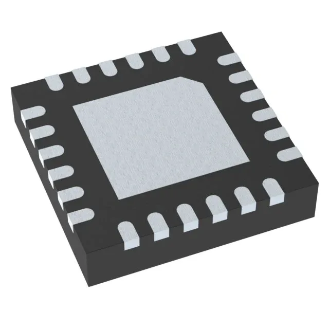
Automotive dual-rail regulator for positive and negative supplies
It combines a boost converter for the positive output and a buck-boost converter for the negative output, all in a 24-VQFN (4x4 mm) package. This part is built for automotive infotainment, cluster, and ADAS camera modules that need a clean bipolar supply from a single battery rail — think op-amp rails, LCD bias, or sensor front-ends.
What the 1.7 A switch rating means for your load budget
The 1.7 A switch current rating is the peak current the internal power switch can handle — not the output current. In a boost converter, output current is lower than switch current by the duty-cycle factor. For a 5 V output from a 3.3 V input, expect roughly 1 A available on the positive rail before the switch current limit is reached. The negative buck-boost rail will deliver less, typically 0.5 A to 0.7 A depending on input-to-output ratio. Compared to single-output automotive bucks like the LMR33630APCQRNXRQ1 (3 A, synchronous) or LMS3655MQURNLRQ1 (5.5 A, non-synchronous), the TPS65131TRGERQ1 trades raw current for the ability to produce a negative rail. If your BOM only needs a positive buck, those peers are simpler and more efficient. If you need both +V and -V from one IC, the TPS65131TRGERQ1 is the only AEC-Q100 option in this comparison.
Active production — sourcing and lifecycle posture
Store the reels in a dry cabinet below 30°C / 60% RH; the VQFN is moisture-sensitive per JEDEC level 3.
Temperature grade and application environment
If the application sees sustained junction temperatures above 105°C — for example, near an exhaust manifold or in a transmission controller — the LMS3655MQURNLRQ1 (rated to 150°C TJ) is a better fit, though it is single-output buck only. The non-synchronous architecture means an external Schottky diode is required for each output. The 1.38 MHz switching frequency is fixed — no frequency synchronization to an external clock.