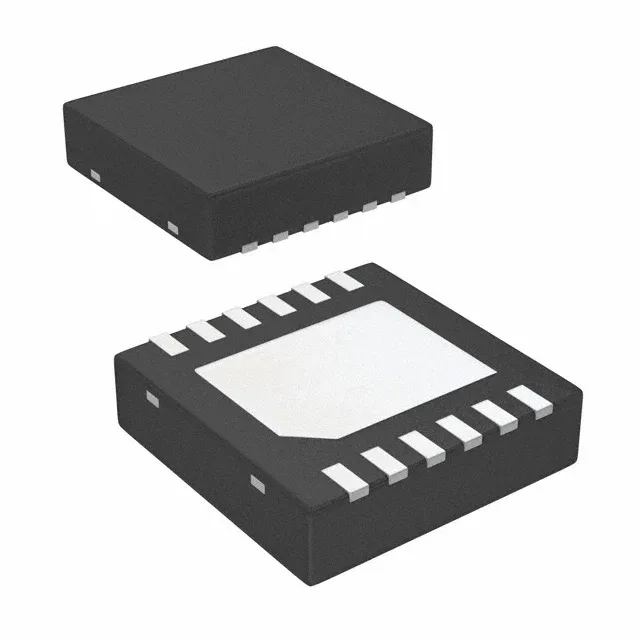
Negative rail generation with the TPS63710DRRT
The TPS63710DRRT is a Texas Instruments inverting buck regulator that produces a regulated negative output from a positive input rail — a common requirement when biasing GaAs FETs, op-amp supplies, or LCD bias in equipment where a separate negative supply isn't available. Input range spans 3.1 V to 14 V, and the adjustable output can be set anywhere from -1 V down to -5.5 V using an external resistor divider. The 1 A continuous output covers most auxiliary negative rail loads. Switching at 1.5 MHz keeps the inductor and capacitor values small, which helps when board space is tight.
Sourcing and package details
The ROHS3 compliance is current with EU directives.
What the 1.5 MHz switching means for your layout
The 1.5 MHz switching frequency lets you use a 2.2 µH to 4.7 µH inductor in the 1210 or 2012 footprint, keeping the power stage compact. The trade-off is that the fast edges demand careful layout — keep the switch node loop short and the input bypass capacitor close to the IC's VIN and GND pins. Because the output is negative, the traditional buck inductor and output capacitor connect between the SW pin and the negative output rail, not to ground. The feedback divider references the negative output, so the resistor values must be calculated with the output voltage polarity in mind.