Buck-boost regulator for single-cell battery rails
The output is adjustable from 2.5 V up to 5.5 V, making it a natural fit for battery-powered gear where the input voltage swings above and below the regulated rail — think a single Li-ion cell powering a 3.3 V sensor node or a 5 V USB peripheral.
Sizing the output for your load budget
The 500 mA output current is the headline number for BOM sizing. In a buck-boost topology, the input current can exceed the output current when the input voltage is low — at 2.5 V in and 3.3 V out, the input draw is roughly 660 mA plus switching losses, so the upstream supply and PCB traces need to handle that peak. That means the divider resistors also set the minimum load for stability — a light-load condition below a few mA may push the part into pulse-skip mode, which is fine for battery life but adds ripple.
The ROHS3 compliance is confirmed. For prototyping, a breakout board or a pre-assembled module is the easier path.
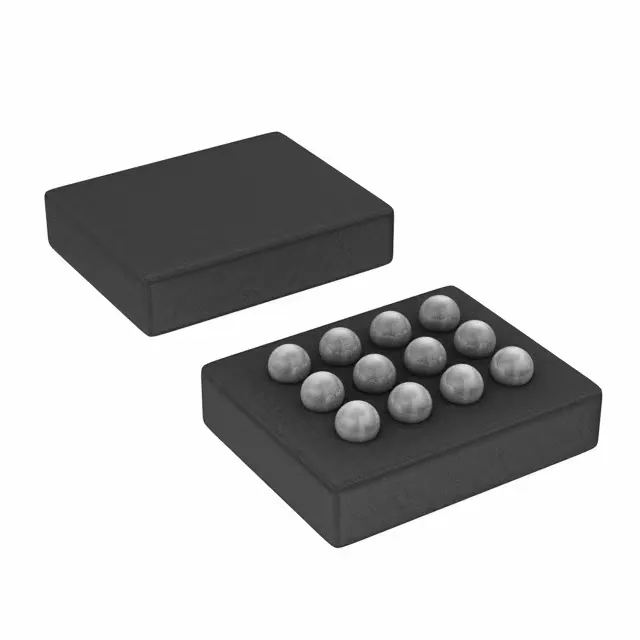
The 12-DSBGA package measures roughly 1.6 mm × 1.2 mm with 0.4 mm ball pitch. That footprint demands a 2-layer or 4-layer PCB with micro-vias for fan-out — the centre balls carry the switch node and output, so thermal vias under the package help with heat spreading. If the board sits near a hot motor or in direct sun, check the junction temperature derating.