What the 2A switch rating means for your load
The TPS63010YFFR integrates a 2A switch in a buck-boost topology, meaning the inductor current limit is the hard ceiling for the output. For a 1.8 A continuous load at 3.3 V from a 3.7 V Li-ion battery, the switch current will be close to the limit during step-up — budget derating and check the inductor saturation current against the peak switch current.
Input and output voltage envelope
Input range is 2V to 5.5V, covering single-cell Li-ion, 3.3V and 5V rails. Output is adjustable from 1.2V to 5.5V — the feedback divider sets the voltage; the datasheet gives the resistor values for common outputs.
Switching frequency and external component sizing
Fixed 2.4 MHz switching frequency lets you use a 1 µH to 2.2 µH inductor and 10 µF output capacitor — small enough for space-constrained designs. The trade-off is that the high-frequency loop must be physically tight on the PCB; the DSBGA package places the switch node and input cap close, but the layout must keep the ground return path short to avoid ringing that eats into the efficiency.
Package and layout constraints
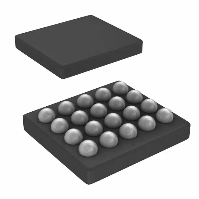
The 20-DSBGA package has a 0.4 mm ball pitch — a 4-layer PCB with microvias is the practical minimum for fan-out. Two-layer boards will struggle to route all signals and may force vias under the package, which is not recommended.
Production status and ordering
It is ROHS3 compliant.