1.6 A switch current — what it buys the rail
That switch current rating sets the ceiling for output current in both step-up and step-down modes — at lower Vin-to-Vout ratios the available output current is higher, but the 1.6 A figure is the hard limit before the current-limit comparator trips. For a 3.3 V rail from a single Li-ion cell (2.7 V to 4.2 V), this part comfortably sources 800 mA to 1 A continuous, which covers most sensor-node and portable-radio loads.
1.25 MHz to 1.5 MHz — inductor sizing trade-off
The switching frequency range of 1.25 MHz to 1.5 MHz lets you use a small 2.2 µH to 4.7 µH inductor, keeping the total solution footprint under 25 mm² including passives. Higher frequency means lower ripple current through the inductor, but also higher switching losses in the FETs and more edge-rate energy to decouple.
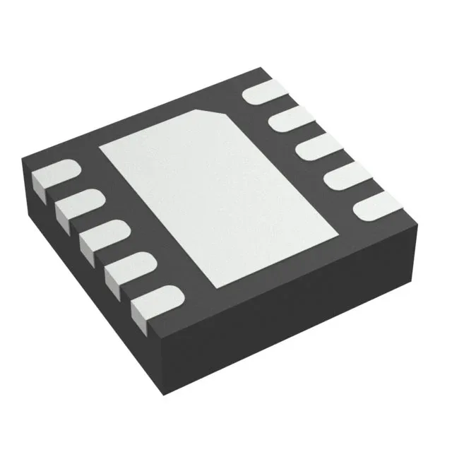
10-VSON exposed pad — thermal and layout note
The 10-VSON package (3 mm × 3 mm) with exposed pad requires a thermal-land pattern on the PCB with at least four via-in-pad connections to the ground plane. The pad is the main heat path — the plastic body alone cannot sink the 1.6 A switch losses.