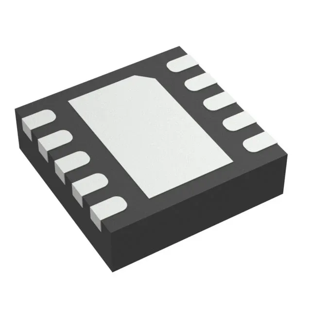
Buck-boost regulator for single-cell Li-ion to 3.3V rail
The Texas Instruments TPS63000DRCRG4 is a buck-boost switching regulator that can step a voltage up or down — it regulates the output above, below, or equal to the input. That is the whole point of a buck-boost topology: a single-cell Li-ion battery starts at 4.2 V fresh off the charger, spends most of its life around 3.6 V, and drops to 3.0 V before the protection circuit cuts it off. This part holds a 3.3 V rail through that whole discharge curve without a second converter.
The 1.6 A switch current rating is the peak current the internal NMOS and PMOS switches can handle cycle-by-cycle. It is not the continuous output current — that depends on the input-to-output voltage ratio and the inductor value. At a 3.3 V output from a 3.6 V Li-ion cell, you can expect around 1 A continuous output before the switch current limit folds back. For a 5 V output from the same cell, the output current drops to roughly 800 mA because the boost ratio demands more switch current. Plan your load budget accordingly.
1.25 MHz to 1.5 MHz switching — inductor and layout considerations
The switching frequency runs between 1.25 MHz and 1.5 MHz, which keeps the inductor small — a 2.2 µH to 4.7 µH shielded ferrite is typical. That frequency also pushes the switching noise above the AM band, so it is easier to filter for RF-sensitive loads. The downside: the 10-VSON (3x3) exposed-pad package needs a solid thermal connection to the PCB ground plane.