800 mA at 3 MHz — the load-budget and footprint trade-off
The TPS62693YFDR is a synchronous step-down (buck) regulator from Texas Instruments that delivers a fixed 2.85 V output at up to 800 mA from a 2.3 V to 4.8 V input rail.
Why the 3 MHz switching frequency matters for your BOM
A 3 MHz switching frequency pushes the fundamental ripple above the AM radio band and into a range where small, low-profile inductors (e.g., 1.0 mm height) and 10 µF to 22 µF ceramic output caps can keep the output ripple within spec. This shrinks the total converter footprint compared to a 1 MHz or 500 kHz design, at the cost of slightly higher switching losses in the internal FETs — a trade-off that favours space-constrained, moderate-load applications.
Fixed 2.85 V output — one less resistor divider
The output is factory-set to 2.85 V (fixed), so no external feedback resistor network is required. That saves two resistors and one feedback-node capacitor from the BOM, and eliminates the tolerance stack of the divider from the output accuracy budget.
6-DSBGA package — layout and assembly considerations
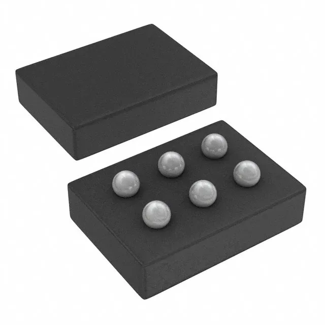
The 6-bump DSBGA (0.4 mm pitch, approximately 1.2 mm × 0.9 mm body) requires a fine-pitch stencil and a reflow profile tuned for lead-free solder. The small thermal mass means the part heats up quickly — the recommended land pattern and solder paste coverage are detailed in the datasheet layout section.
Operating temperature range and environment
The synchronous rectifier (integrated) improves efficiency at light loads, which helps keep the die temperature down in a sealed enclosure.