600 mA buck at 6 MHz — what the switching frequency buys you
The TPS62620YFFT: The 6 MHz switching frequency shifts the inductor and capacitor values down — a 1 µH inductor and 4.7 µF output cap are typical, saving board area in space-constrained portable designs. The synchronous rectifier (on-chip low-side FET) improves efficiency at light loads compared to a diode-based buck, which matters for battery-powered gear where the load spends most of its time in standby or idle.
Package and board-fit realities for the 6-DSBGA
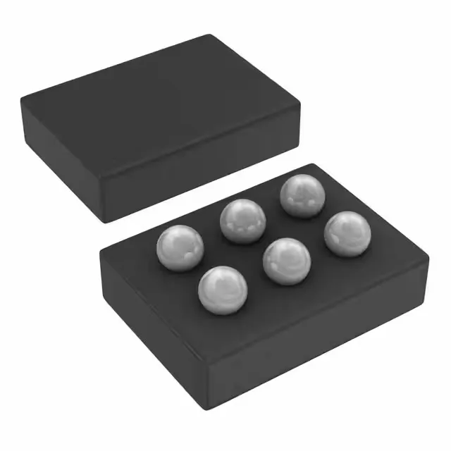
The 6-DSBGA (0.4 mm ball pitch, 6 bumps) is a wafer-level chip-scale package — the die is essentially the package. This means the PCB footprint is the ball pattern; there is no molded body to handle. Stencil aperture design and solder paste volume are critical for assembly yield; a 0.125 mm stencil thickness with 1:1 aperture-to-pad ratio is a common starting point. For an outdoor IoT node that sees 85 °C ambient, the junction temperature stays within the silicon limit at 600 mA load with proper PCB copper spreading.
Active lifecycle and procurement posture
No stock-holding claim is made; each order is verified against the buyer's quantity and delivery window.