6 MHz switching — why the inductor shrinks
That switching frequency is the headline spec: it lets you use a sub-1 µH inductor and a small ceramic output cap, saving board area where a slower 1–2 MHz regulator would need a larger LC pair. The trade-off is switching losses that cap the efficiency at light loads, but for a 600 mA rail in a tight space, the footprint win usually wins.
Rated for 600 mA continuous output, this part is sized for a single low-power rail — a sensor supply, a Bluetooth module, or the core voltage of a small MCU. It is not a bulk converter for a multi-amp load; the 6-DSBGA package cannot sink the heat of a 1 A+ output without the junction climbing past 85°C.
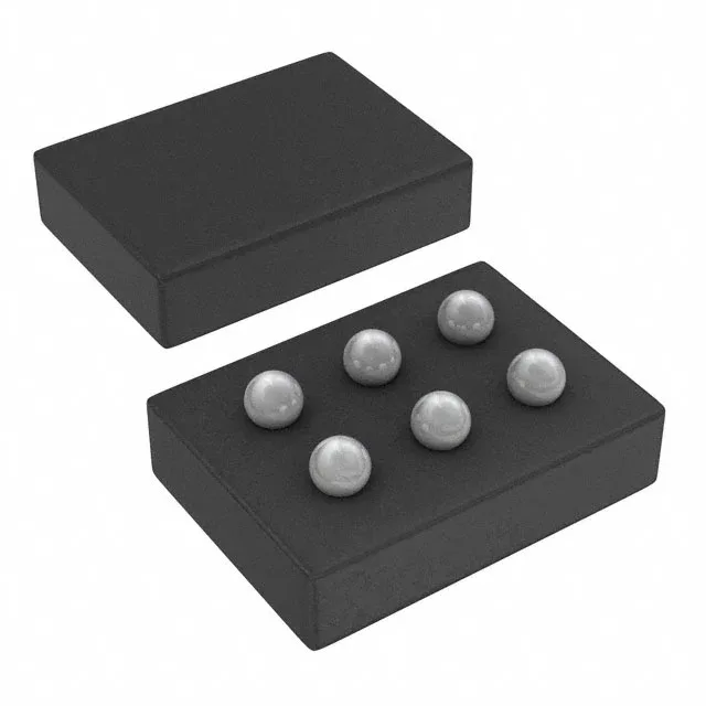
6-DSBGA — layout and rework realities
The 6-DSBGA package (0.4 mm pitch, 0.8 mm × 1.2 mm body) is the smallest footprint for this function, but it demands a controlled reflow profile and a microscope for inspection. For rework, a hot-air nozzle sized to the package body and a preheat plate at 125°C are standard; the part is MSL-1 per the TI datasheet, so no bake is needed if the reel seal is intact.