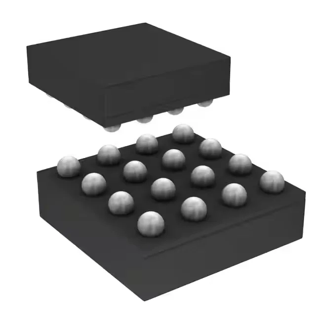
2.5 MHz switching — why it shrinks the inductor
The TPS62366AYZHT switches at 2.5 MHz, which lets you use a much smaller inductor than a 500 kHz or 1 MHz regulator. For a 2.5 A rail, that typically means a 1 µH to 2.2 µH chip inductor in a 0805 or 0603 footprint — the whole supply fits in a corner of the board. The trade-off: switching losses go up with frequency, so efficiency drops a few points at light load compared to a slower part. But if board area is the constraint, this is the right choice.
2.5 A output — load headroom and thermal reality
Rated for 2.5 A continuous output, this regulator can power a modern SoC core, FPGA rail, or a cluster of DDR termination loads. The 2.5 A ceiling is the peak continuous current; pulsed loads above that need the datasheet transient response curves checked. At 2.5 A full load, expect the junction to rise 40–50 °C above ambient if the board has a solid ground plane.
Sourced per RFQ — confirm the BOM quantity and preferred package option at quote time.
Programmable output — 0.5 V to 1.77 V via I²C
The output voltage is adjustable from 0.5 V to 1.77 V, with preset start-up options at 1.16 V and 1.2 V. The adjustment is done through an I²C interface — no external resistor divider needed. This is useful for dynamic voltage scaling or for a single BOM that serves multiple core voltages.