3 MHz synchronous buck — small solution for 1.5 V rails
The high switching frequency lets you use a 1 µH or smaller inductor and a 4.7 µF output capacitor, keeping the total solution footprint under 15 mm² — useful when board area is tight and the load is a 1.5 V core rail.
Input range and output — Li-ion to 5 V rail
The 2.7 V minimum input covers a single Li-ion cell through its discharge curve; the 6 V maximum handles a regulated 5 V bus with margin. The fixed 1.5 V output is set internally — no external divider network, so the BOM stays at one inductor, two capacitors, and the IC. Synchronous rectification eliminates the external Schottky diode and keeps efficiency above 90% at moderate loads.
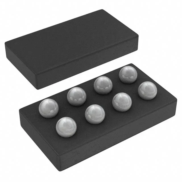
TI lists the TPS62321YZDR as obsolete. The 8-DSBGA package is a 0.5 mm pitch wafer-level chip-scale package; the copper pad layout on the PCB must match the TI recommended footprint for reliable solder joints.