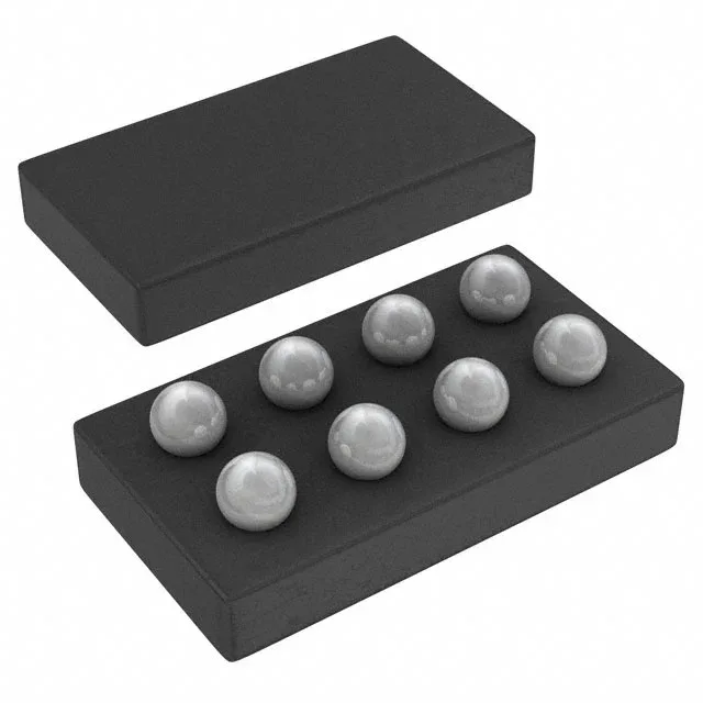
The TPS62305YZDT is a fixed-output step-down (buck) converter from Texas Instruments, delivering 500 mA at 1.875 V from an input range of 2.7 V to 6 V. The 1.875 V rail is a non-standard voltage — not 1.8 V, not 3.3 V — so it is almost certainly powering a specific core or I/O supply on a mixed-signal ASIC or FPGA that requires that exact level. If the load is a 1.8 V nominal device, check the tolerance; 1.875 V is 75 mV above 1.8 V and may exceed the absolute-maximum rating of a 1.8 V-only pin.
3 MHz switching — inductor size and ripple trade-off
The 3 MHz switching frequency lets the design use a small-value inductor (typically 1 µH to 2.2 µH) in a 0805 or smaller footprint, which keeps the total solution area tight — important for the 8-DSBGA package that already shrinks the PCB real estate. The trade-off: 3 MHz switching pushes the switching losses up and the efficiency down at light loads compared to a 1 MHz part, but the synchronous rectifier helps recover some of that loss by replacing the freewheeling diode with a low-Rds(on) FET. For a 500 mA load at 1.875 V out, expect efficiency in the mid-80s at full load from a 3.6 V input.
Input range: 2.7 V min — battery and USB compatibility
The 2.7 V minimum input means the part can run from a single Li-ion cell (3.0 V to 4.2 V) down to near its end-of-discharge voltage, or from two alkaline cells in series. The 6 V maximum covers USB bus power (5 V ±10 %) and regulated 5 V rails. If the input is a battery, the 2.7 V undervoltage lockout threshold prevents deep discharge; if the input is a 5 V rail, the 1.875 V output leaves 3.125 V dropout headroom — the buck operates in continuous conduction mode with no dropout concern.