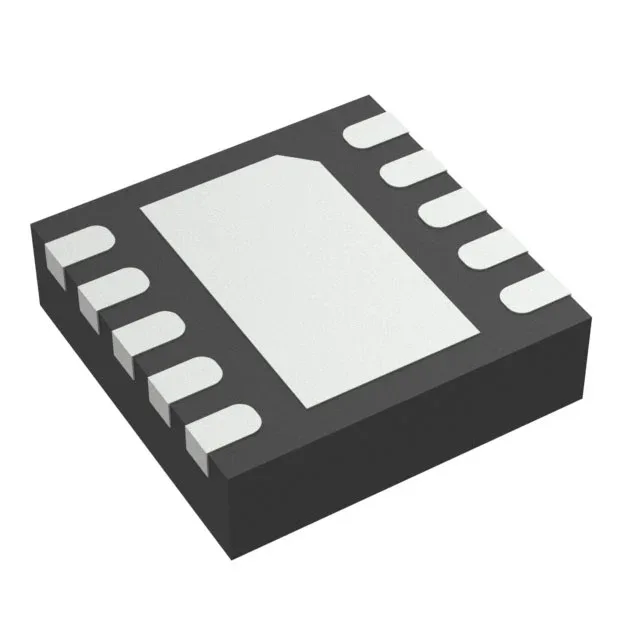
Texas Instruments TPS62301DRCRG4 — Power Management (PMIC / Gate Driver)

TPS62301DRCRG4 Buck Converter, 3 MHz, 500 mA

MPNTPS62301DRCRG4
End of Life

Texas Instruments TPS62301DRCRG4, Step-Down Buck Converter, Fixed 1.5 V Output, 500 mA, 3 MHz Switching Frequency, 10-VSON (3x3) Package, -40°C to 85°C.

StockContact for availability
MOQ1 pcs
  • 100% new & originalTraceable channels only — no refurbs, no pulls, no remarked parts.
  • Date & lot codes on quoteStated per line before you commit; label photos on request.
  • MSL-compliant ESD packingMoisture-sealed bags with indicator cards; reels photo-verified.
  • PayPal buyer protectionPay by T/T, PayPal or Payoneer — card payments covered end to end.

Specifications

TPS62301DRCRG4 Technical Specifications
ParameterValue
Output typeFixed
Mounting typeSurface Mount
Voltage - input2.7V
Voltage - output (Min (Fixed))1.5V
Current - output500mA
Frequency3MHz
Number of outputs1
Operating temperature-40°C~85°C(TA)
PackageTape & Reel (TR)
FunctionStep-Down
TopologyBuck
Case10-VFDFN Exposed Pad
Output configurationPositive
Synchronous rectifierYes

Product details

Fixed 1.5 V at 500 mA — the BOM-fit check

The TPS62301DRCRG4 is a fixed-output step-down (buck) converter from Texas Instruments, delivering 500 mA at a regulated 1.5 V from an input rail between 2.7 V and 6 V. The 3 MHz switching frequency lets the designer use a small inductor and output capacitor, shrinking the total solution footprint for space-constrained boards.

At 3 MHz the switching period is about 330 ns, so the inductor ripple current stays manageable with values in the 1 µH to 2.2 µH range. That keeps the inductor physically small — typically a 2.5 mm × 2.0 mm shielded type — and the output capacitor in the 10 µF to 22 µF ceramic class. The synchronous rectifier eliminates the external Schottky catch diode, saving one component and one placement step.

Package and thermal: 10-VSON with exposed pad

The 10-VSON (3 mm × 3 mm) package has an exposed thermal pad on the bottom. The datasheet recommends a 2.6 mm × 2.6 mm copper land on the PCB with at least four thermal vias to the ground plane. Without that pad soldered to a copper pour, the junction-to-ambient thermal resistance rises and the 500 mA output at high ambient temperature may push the die past the 85°C operating limit.

Frequently asked questions

Does TPS62301DRCRG4 need an external inductor?

Yes, like any non-module buck converter, it requires an external inductor and output capacitor. The 3 MHz switching frequency allows a small inductor, typically 1 µH to 2.2 µH. The synchronous rectifier is internal, so no external catch diode is needed.