2.25 MHz switching buys inductor space
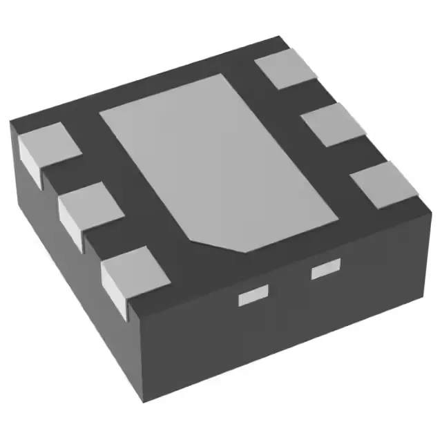
The TPS62260DRVT is a 600 mA step-down (buck) converter from Texas Instruments that switches at 2.25 MHz. That frequency lets the designer use a 1 µH to 2.2 µH inductor — typically a 2.0 mm × 1.6 mm or smaller chip inductor — instead of the 4.7 µH to 10 µH part a 500 kHz regulator would need. For a board where every mm² of height-constrained area is spoken for, the 2.25 MHz rate is the primary space-saving lever.
Input and output window — what fits
The input range runs from 2 V to 6 V, so a single Li-ion cell (3.0 V to 4.2 V), a 3.3 V rail, or a 5 V rail all work as the source. The output is adjustable from 0.6 V up to the input voltage, set by a resistor divider on the FB pin. A 3.3 V output — the most common ask — is within reach as long as the input stays above about 3.8 V to leave headroom for the high-side switch dropout.
Synchronous rectifier — one fewer diode on the BOM
The TPS62260 integrates a synchronous rectifier, so there is no external Schottky catch diode. That saves about 6 mm² of board area and one line item on the BOM. At light loads the device enters power-save mode, reducing the switching frequency to maintain efficiency — the synchronous FET stays on during the off-time, which keeps the efficiency curve above 80 % down to a few mA of load.