DCS-Control architecture and the 2.25 MHz switching rate
Texas Instruments' DCS-Control topology combines hysteretic and voltage-mode control to deliver fast transient response with minimal output capacitance. The 2.25 MHz switching frequency keeps the inductor and capacitor values small — a 1 µH to 2.2 µH inductor and a 10 µF ceramic output cap are typical for a 3.3 V rail at 500 mA. This switching rate also stays above the AM radio band, which simplifies EMI filtering in 24 V industrial bus-powered designs.
Input range and output adjustability — 3 V to 17 V in, 0.9 V to 6 V out
The 3 V minimum input covers single-cell Li-ion and 3.3 V regulated rails; the 17 V maximum handles 12 V unregulated supplies and 5 V with headroom. The adjustable output from 0.9 V to 6 V lets the same part serve 1.2 V core rails, 1.8 V I/O, 3.3 V analog, or 5 V peripheral buses. The 500 mA output rating is continuous — no pulse-skipping headroom games at the top of the range.
Package footprint — 8-WSON with exposed pad
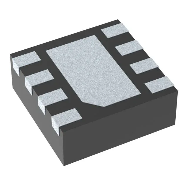
The 8-WSON (2x2 mm) package with exposed thermal pad requires a PCB land pattern that connects the pad to a copper plane for heat spreading. The datasheet recommends a 2.2 mm x 2.2 mm pad with at least four thermal vias to the inner ground layer. Without that thermal relief, the junction-to-ambient thermal resistance rises above the 60 °C/W typical, and the 500 mA output at high ambient temperature derates earlier than expected.