3 MHz switching — inductor shrinks, but layout matters
The TPS62060DSGT is a synchronous step-down (buck) converter from Texas Instruments that switches at 3 MHz, which lets you use a smaller inductor than a lower-frequency part — typically a 1 µH to 2.2 µH chip inductor in a 0805 or smaller footprint. The 1.6 A continuous output covers moderate loads like an FPGA core rail, a sensor array, or a wireless module supply.
Input range: 2.7 V min, 6 V max — Li-ion or 5 V rail
The input voltage range runs from 2.7 V up to 6 V. That 2.7 V minimum lets it run from a single-cell Li-ion battery down to near-discharge; the 6 V maximum covers a regulated 5 V bus with margin. The adjustable output starts at a 0.8 V reference, so you can set it for 1.2 V, 1.8 V, 3.3 V, or anything in between with a resistor divider.
Synchronous rectifier — no external Schottky needed
The integrated synchronous rectifier eliminates the external catch diode, which saves board space and improves efficiency at low output voltages. The 3 MHz switching frequency pushes the switching losses, but the synchronous FETs keep the efficiency above 90% for most of the load range.
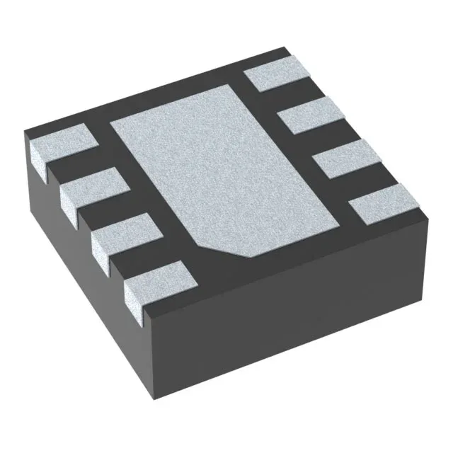
Package and thermal: 8-WSON with exposed pad
For 1.6 A output at high step-down ratios, the thermal pad must connect to a solid ground plane with multiple vias — the datasheet layout recommendation is worth following closely.