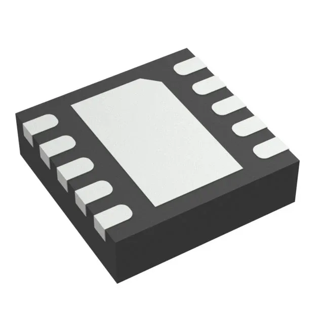
Texas Instruments TPS62040DRCRG4 — Power Management (PMIC / Gate Driver)

TPS62040DRCRG4 Buck Converter, 1.2 A, 1.25 MHz, Synchronous

MPNTPS62040DRCRG4
End of Life

Texas Instruments TPS62040DRCRG4, step-down (buck) DC-DC converter, 1.2 A output, 1.25 MHz switching frequency, synchronous rectification, adjustable output from 0.7 V, 2.5 V to 6 V input, -40°C to 85°C, 10-VSON (3x3 mm) package, Tape & Reel.

$50.4500Ref. price · indicative, final on quote
Independent supplier — new & surplus stockAuthenticity-screened · ESD-safe packingListing updated Jul 2026

Specifications

TPS62040DRCRG4 specifications
ParameterValue
Output typeAdjustable
MountingSurface Mount
Voltage - input2.5V
Voltage - output6V
Voltage - output (Min (Fixed))0.7V
Output current1.2A
Frequency - switching1.25MHz
I/O channels1
Operating temperature-40°C~85°C(TA)
PackageTape & Reel (TR)
FunctionStep-Down
TopologyBuck
Case10-VFDFN Exposed Pad
Output configurationPositive
Synchronous rectifierYes

Product details

1.2 A synchronous buck in a 3×3 mm VSON

It integrates a synchronous rectifier, so no external Schottky diode is needed for the low-side path — a clear BOM simplification for point-of-load rails in portable or space-constrained designs.

Switching at 1.25 MHz — inductor and capacitor sizing

The 1.25 MHz switching frequency lets the designer use a small inductor, typically in the 2.2 µH to 4.7 µH range, and keep output capacitance under 22 µF. That shrinks the total footprint around the 10-VSON (3×3 mm) package — a meaningful advantage when board area is the constraint. Output is adjustable from a 0.7 V reference up to the input voltage. For a 1.8 V rail — a common core or I/O supply — the feedback divider uses two resistors; the part can deliver that voltage across the full 1.2 A load.

Frequently asked questions

Can TPS62040DRCRG4 output 1.8 V?

Yes. Setting the feedback divider resistors for 1.8 V is straightforward, and the part can deliver the full 1.2 A at that voltage across its operating temperature range.