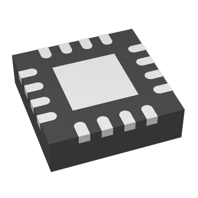
85V boost in a 3x3 QFN — what it does
The TPS61390RTER is a single-output step-up (boost) regulator that converts a 2.5V to 5.5V input rail into an adjustable output from 20V up to 85V. That voltage ceiling — 85V max — is the headline reason to reach for this part: most boost converters top out around 40V or 60V.
Switching frequency and inductor sizing
At 700 kHz the switching period is about 1.4 µs — fast enough that a 6.8 µH inductor handles the ripple current for most output-voltage targets below 60V. The non-synchronous topology (external Schottky diode required) adds a diode drop to the efficiency but keeps the BOM cost low and avoids the high-side FET complexity of a synchronous boost at these voltages.
Temperature range and package handling
The 0.5 mm pitch requires a 4-layer board for reliable fan-out; a 2-layer board can work for lower pin-count designs but risks solder-bridging on the thermal pad.
Sourcing posture — active and available to order
No stock-holding claim — every order is procured per RFQ.