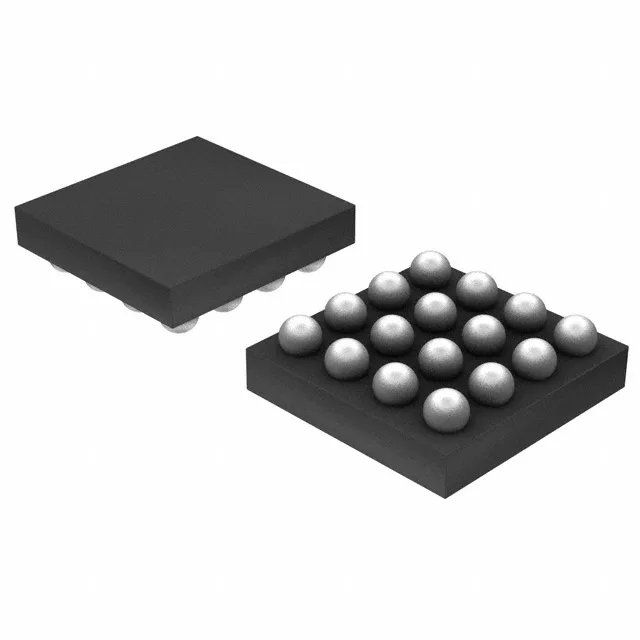
Boost converter for tight spaces and high-voltage rails
Switching frequency runs between 1.2 MHz and 1.7 MHz, which keeps the inductor small — useful when the PCB real estate is the constraint.
What the switching frequency and output range mean for the BOM
The 1.2 MHz to 1.7 MHz switching band lets you pick an inductor in the 2.2 µH to 4.7 µH range — small footprint, low profile. The output can be set anywhere from 5 V (minimum fixed) up to 16 V via the feedback divider, so the same part covers a 5 V rail, a 12 V sensor supply, or a multi-LED string. Synchronous rectification drops the forward-drop loss you would see with a catch diode; at 3.3 V in, 5 V out, that gain is worth a couple of percent in efficiency.
Package and thermal reality for the DSBGA
The 16-DSBGA is a 0.4 mm pitch, wafer-level chip-scale package — no mould compound, the die backside is the top surface. The junction temperature rating goes to 125 °C, but the thermal path is through the solder balls to the PCB copper. A four-layer board with thermal vias under the package is the baseline for any continuous load above a few hundred milliamps. The tape-and-reel delivery is standard for this package class; reflow profile follows the JEDEC J-STD-020 for MSL level on the reel label.