PWM dimming on the LED channels gives the host processor fine-grained control over flash intensity and torch brightness — useful for exposure balancing and video light modes.
2 MHz switching — inductor and capacitor sizing
The 2 MHz switching frequency lets the designer use a small, low-profile inductor — typically 1 µH to 2.2 µH in a 0603 or 0805 case — and ceramic input/output capacitors in the 4.7 µF to 10 µF range. That keeps the total solution footprint under 25 mm², which matters when the board real estate around the camera module is already tight.
Three outputs and flash current — what the ratings mean
Three independent current sinks let the part drive a multi-LED flash array or separate flash/torch/VIO paths from a single boost rail. The 890 mA flash rating per channel is the peak current during the flash event; the 445 mA continuous rating covers torch mode. Both are set by external resistors, so the BOM can be tuned for the LED's maximum rated pulse width and duty cycle without changing the IC.
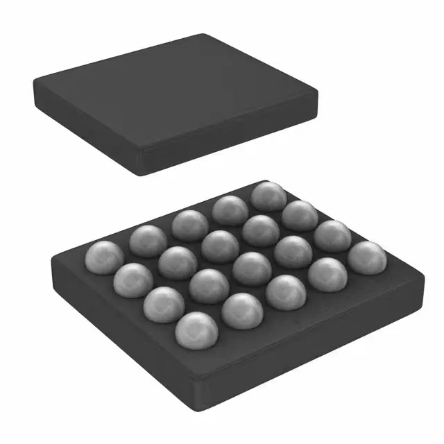
Housed in a 20-bump DSBGA (0.4 mm pitch) — the same footprint as the TPS61325YFQR variant — the part demands a controlled solder profile and X-ray inspection after reflow.