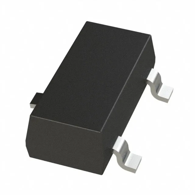
Boost converter in a three-pin SOT-23
The TPS61322DBZT is a fixed-output step-up regulator from Texas Instruments that delivers a regulated 2.2V rail from an input as low as 0.9V — think single-cell alkaline, NiMH, or Li-ion that has run down to its cutoff. The 1.2A switch current rating in a SOT-23-3 package means you can pull useful power out of a small board area without needing a bigger inductor or external FET. Synchronous rectification keeps efficiency up at moderate loads — the internal low-side and high-side switches replace the usual external Schottky diode, saving a component and a diode drop. Switching frequency spreads from 500 kHz to 2 MHz, letting you trade inductor size against switching losses.
The 1.2A switch current is the peak current the internal FET can handle cycle-by-cycle. For a boost converter, the input current is higher than the output current — at 2.2V out from a 1.2V input, the switch sees roughly 2× the output current. So a 500 mA load at 2.2V pulls about 1A from the input, which is within the switch limit but leaves little headroom for transients. Size the inductor for the peak current, not the average. Minimum input of 0.9V means the part starts up from a nearly dead battery. The undervoltage lockout is inside that range — the part shuts down cleanly below the threshold rather than browning out the load. Maximum input of 5.5V covers the full Li-ion range (3.0V to 4.2V) plus a 5V USB rail, but not 12V or higher. The SOT-23-3 package has a small thermal mass — at high output current the junction temperature rises quickly, so derate the output current above 85°C ambient using the datasheet thermal curves.
Texas Instruments has not issued a last-time-buy or end-of-life notice for this order code. ROHS3 compliant. Sourcing is straightforward — we quote against the BOM quantity. The SOT-23-3 footprint is widely second-sourced, but the fixed 2.2V output and synchronous rectifier are specific to this TI part number.