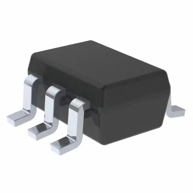
Texas Instruments TPS61222MDCKTEP — Power Management (PMIC / Gate Driver)

TI TPS61222MDCKTEP Boost Converter, 0.7V-5.5V Input

MPNTPS61222MDCKTEP
Active

Texas Instruments TPS61222MDCKTEP, Step-Up Boost Converter, Fixed 5V Output, 0.7V to 5.5V Input, 200mA Switch, Up to 2MHz, SC-70-6, -55°C to 125°C.

$18.1200Ref. price · indicative, final on quote
StockContact for availability
MOQ1 pcs
  • 100% new & originalTraceable channels only — no refurbs, no pulls, no remarked parts.
  • Date & lot codes on quoteStated per line before you commit; label photos on request.
  • MSL-compliant ESD packingMoisture-sealed bags with indicator cards; reels photo-verified.
  • PayPal buyer protectionPay by T/T, PayPal or Payoneer — card payments covered end to end.

Specifications

TPS61222MDCKTEP Technical Specifications
ParameterValue
Output typeFixed
Mounting typeSurface Mount
Voltage - input5.5V
Voltage - output (Min (Fixed))5V
Current - output200mA (Switch)
FrequencyUp to 2MHz
Number of outputs1
Operating temperature-55°C~125°C(TJ)
PackageTape & Reel (TR)
FunctionStep-Up
TopologyBoost
Case6-TSSOP, SC-88, SOT-363
Output configurationPositive
Synchronous rectifierYes

Product details

Boost converter for harsh-environment battery applications

The Texas Instruments TPS61222MDCKTEP is a step-up (boost) DC-DC converter that delivers a fixed 5V output from an input as low as 0.7V and up to 5.5V. It integrates a 200mA switch and synchronous rectifier in a 6-pin SC-70-6 package.

What the 0.7V minimum input means for your battery selection

A 0.7V minimum input lets this part start up and regulate from a single alkaline cell (nominal 1.5V, end-of-life ~0.9V) or a Li-ion cell deep into discharge. The 5.5V input maximum covers USB power, 2-cell alkaline stacks, and regulated 3.3V or 5V rails without risk. The 200mA switch current limit sets a practical output power ceiling of roughly 1W at 5V — enough for a sensor node, RF transmitter, or small microcontroller rail.

Up to 2MHz switching — inductor sizing and noise

Switching at up to 2MHz lets the designer use small, low-profile inductors (typically 2.2µH to 4.7µH) and ceramic output capacitors, shrinking the total solution footprint. The synchronous rectifier improves efficiency at light loads compared to a diode-based boost, which matters for battery life in always-on applications. The high switching frequency pushes the fundamental switching noise above the AM radio band, simplifying input filter design in sensitive RF systems.

Frequently asked questions

What is the switching frequency of TPS61222MDCKTEP?

The switching frequency is up to 2MHz. This allows the use of small inductors (2.2µH to 4.7µH typical) and ceramic output capacitors, reducing the overall power-supply footprint.