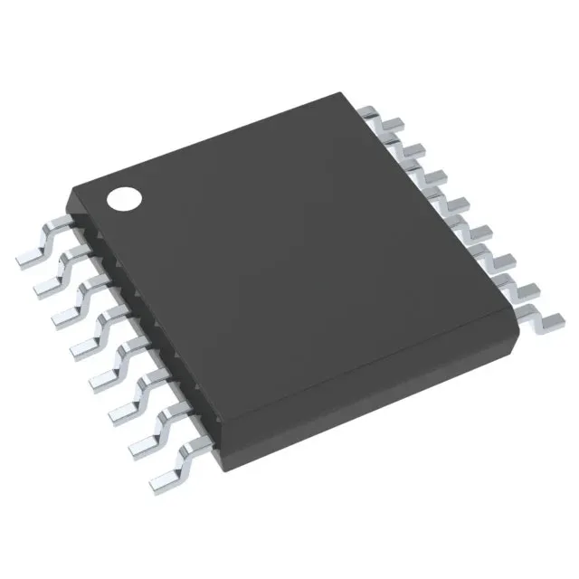
Texas Instruments TPS61130PW — Power Management (PMIC / Gate Driver)

TPS61130PW Buck-Boost + LDO, 500kHz, 16-TSSOP

MPNTPS61130PW
Active

Texas Instruments TPS61130PW, Dual-Output Power Management IC, Step-Down/Step-Up (Buck/Boost) 300mA + Linear (LDO) 320mA, 500kHz Switching Frequency, 1.8V to 5.5V Input, -40°C to 85°C, 16-TSSOP Package.

$7.5700Ref. price · indicative, final on quote
Independent supplier — new & surplus stockAuthenticity-screened · ESD-safe packingListing updated Jul 2026

Specifications

TPS61130PW specifications
ParameterValue
MountingSurface Mount
Supply voltage1.8V ~ 5.5V
Voltage/Current - output 12.5V ~ 5.5V, 300mA
Voltage/Current - output 22.5V ~ 5.5V, 320mA
Frequency - switching500kHz
I/O channels2
Operating temperature-40°C~85°C
PackageTube
TopologyStep-Down/Step-Up (Buck/Boost) (1), Linear (LDO) (1)
W (Sequencer)No
W (LED driver)No
W (Supervisor)No
Case16-TSSOP (0.173\", 4.40mm Width)

Product details

Dual-rail PMIC in a 16-pin TSSOP — what it delivers

The Texas Instruments TPS61130PW packs a 500kHz buck-boost converter and a separate LDO into a single 16-TSSOP package, giving you two regulated outputs from a 1.8V to 5.5V input rail — think single-cell Li-ion, two-cell alkaline, or a 3.3V system bus. Output 1 (the buck-boost) delivers 300mA adjustable from 2.5V to 5.5V; Output 2 (the LDO) delivers 320mA over the same voltage range. That covers the common split-rail scenario: a 3.3V core supply plus a 5V sensor or interface rail from one IC.

500kHz switching — inductor sizing and ripple

The fixed 500kHz switching frequency sets the inductor value and output ripple. At this frequency, a 4.7µH to 10µH shielded inductor keeps the ripple current within 30-40% of the load — a standard selection for the 300mA output. The trade-off: higher frequency would shrink the inductor footprint but push switching losses up; 500kHz is a practical midpoint for efficiency and board area.

No sequencer, no LED driver — what you don't get

This part has no built-in power-up sequencing, no LED driver, and no supervisor. If your design needs sequenced rail enable or a watchdog, you add external logic or a separate supervisor IC. The LDO output is always on when the input is present — the buck-boost enable pin gives you independent control of the first rail.

Frequently asked questions

Does TPS61130PW require external sequencing?

No built-in sequencer. The buck-boost output is enabled via its own enable pin; the LDO output is active whenever the input supply is present. If your application needs sequenced power-up, you must add an external sequencer or use the enable pin to delay the buck-boost rail.

What is the output current capability of TPS61130PW?

Output 1 (buck-boost) is rated for 300mA, and Output 2 (LDO) is rated for 320mA. Both are adjustable from 2.5V to 5.5V. The total load on the LDO output should not exceed 320mA; the buck-boost output is limited to 300mA regardless of the input voltage.