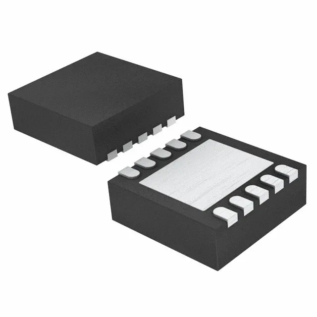
Texas Instruments TPS61093DSKT — Power Management (PMIC / Gate Driver)

TPS61093DSKT Boost Regulator IC – Texas Instruments

MPNTPS61093DSKT
Active

Texas Instruments TPS61093DSKT, boost regulator IC, adjustable output, 1.6 V to 17 V, 900 mA switch, 1.2 MHz fixed switching frequency, 10-WFDFN exposed pad package, active production.

$2.8500Ref. price · indicative, final on quote
Packaging10-WFDFN Exposed Pad
RoHSROHS3 Compliant
Independent supplier — new & surplus stockAuthenticity-screened · ESD-safe packingListing updated Aug 2026

Specifications

TPS61093DSKT specifications
ParameterValue
Output typeAdjustable
MountingSurface Mount
Voltage - input1.6V
Voltage - output17V
Voltage - output (Min (Fixed))1.6V
Output current900mA (Switch)
Frequency - switching1.2MHz
I/O channels1
Operating temperature-40°C~85°C(TA)
PackageTape & Reel (TR); Cut Tape (CT)
FunctionStep-Up
TopologyBoost
Case10-WFDFN Exposed Pad
Output configurationPositive
Synchronous rectifierNo

Product details

Boost regulator with adjustable output up to 17 V

The TPS61093DSKT is a boost converter with an adjustable output from 1.6 V to 17 V from a 1.6 V to 6 V input rail. The 900 mA switch current rating sets the practical output current ceiling. Switching at a fixed 1.2 MHz, the part uses a small inductor and output capacitor, keeping the BOM footprint tight for portable or space-constrained designs. No synchronous rectifier is used, so the external Schottky diode selection matters for efficiency at higher output currents.

Package and thermal path for the 10-SON

The part is not AEC-Q100 qualified.

ROHS3 compliant.

Frequently asked questions

Can the TPS61093DSKT deliver 5 V at 500 mA?

Yes, from a 3.3 V input the 900 mA switch current rating provides enough margin for a 5 V, 500 mA output, assuming typical efficiency above 85 %. The inductor saturation current and Schottky diode rating must be sized for the peak switch current.

What is the switching frequency of the TPS61093DSKT?

The switching frequency is fixed at 1.2 MHz, which allows the use of small inductors and output capacitors, but also means the loop compensation and layout must follow the datasheet guidelines to avoid instability.