600 kHz or 1.2 MHz — the switching frequency is a design lever, not a fixed spec
The TPS61081DRCT is a Texas Instruments boost converter that lets you choose between 600 kHz and 1.2 MHz switching frequency by tying the FREQ pin high or low. That choice directly sets the inductor size and the ripple trade-off: 600 kHz gives better efficiency at heavy loads and a wider input range before pulse-skipping; 1.2 MHz shrinks the inductor footprint and pushes the switching harmonics above the AM band, which matters if the supply shares a board with a radio front-end.
27 V output ceiling — what it buys you
That voltage span covers OLED panel bias, CCD sensor bias in industrial cameras, and multi-LED strings where each string drops 3 V at 20 mA. The 1.3 A switch current limit means the practical output current at 27 V is about 240 mA, assuming 85 % efficiency and a 5 V input — enough for a 6.5 W load before the cycle-by-cycle current limit engages.
Package and thermal: the exposed pad is non-negotiable
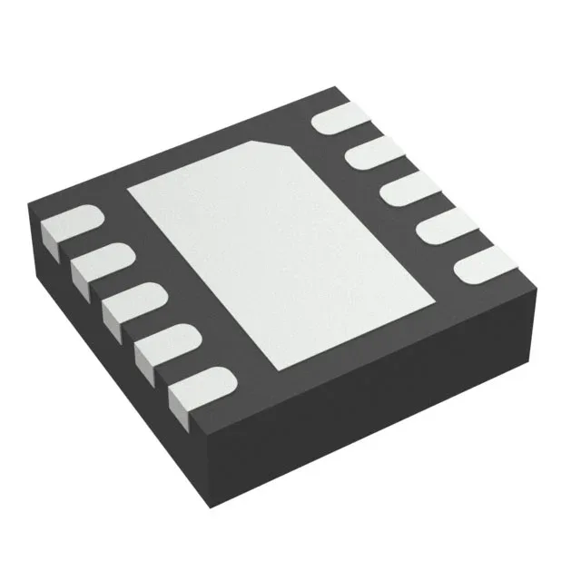
The 10-VSON package (3 mm × 3 mm) has an exposed thermal pad. Without that copper area, the junction temperature rises above the 85 °C operating limit at moderate load.
No synchronous rectifier — external Schottky required
The TPS61081 does not integrate a synchronous rectifier. An external Schottky diode is required between the switch pin and the output. A 30 V, 2 A rated Schottky (e.g., a PMEG3020 or similar) is the typical choice — the forward drop directly affects efficiency, especially at the 1.2 MHz switching rate where reverse-recovery losses in a PN diode would be unacceptable.