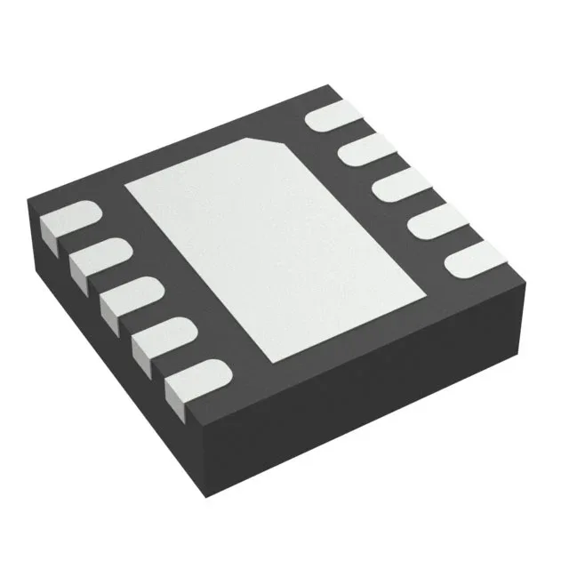
Boost converter for single-cell battery rails
It integrates a 1.5 A switch and uses synchronous rectification to maintain efficiency across the load range. Typical applications include portable devices, battery-powered sensors, and single-cell Li-ion or alkaline systems that need a regulated 5 V rail for USB OTG, sensor modules, or small displays.
Switch current and output power budget
The 1.5 A switch current limit is the hard ceiling for the inductor peak current. For a 5 V output from a 3.3 V input, the maximum continuous output current is roughly 0.9 A, assuming 85% efficiency. If your load pulls more, the converter enters current-limit foldback and the output drops. Size the inductor for a 30% ripple current at the maximum input voltage to keep the peak below the switch limit. Synchronous rectification replaces the output Schottky diode with a low-side FET, cutting forward-conduction losses by 3–5% at moderate loads. This matters most when the battery voltage is near the output — the duty cycle is high and the rectifier conduction time is long.
600 kHz switching and component selection
The 600 kHz switching frequency is a practical middle ground: it allows a 4.7 µH to 10 µH inductor and 10 µF to 22 µF output capacitor in a small footprint, while keeping switching losses low enough for >85% efficiency across most of the load range. The fixed frequency simplifies EMI filtering — the fundamental and its harmonics land predictably.
Without adequate thermal vias, the switch current derates above 70°C ambient.