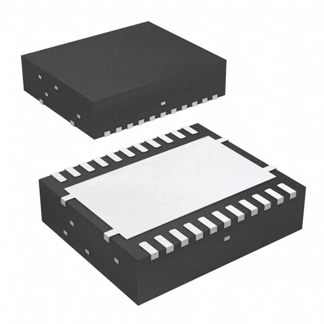
Texas Instruments TPS56221DQPR — DC-DC Power Modules

TPS56221DQPR Buck Converter, 25 A, 4.5-14 V Input

MPNTPS56221DQPR
End of Life

Texas Instruments TPS56221DQPR, Step-Down Buck Regulator, Adjustable Output, 25 A, 4.5 V to 14 V Input, 300/500/950 kHz Switching, Synchronous Rectifier, -40 to 125°C, 22-LSON-CLIP (6x5).

$7.54Ref. price · indicative, final on quote
Packaging22-PowerLFDFN
StockContact for availability
MOQ1 pcs
  • 100% new & originalTraceable channels only — no refurbs, no pulls, no remarked parts.
  • Date & lot codes on quoteStated per line before you commit; label photos on request.
  • MSL-compliant ESD packingMoisture-sealed bags with indicator cards; reels photo-verified.
  • PayPal buyer protectionPay by T/T, PayPal or Payoneer — card payments covered end to end.

Specifications

TPS56221DQPR Technical Specifications
ParameterValue
Output typeAdjustable
Mounting typeSurface Mount
Voltage - input4.5V
Voltage - output13.02V
Voltage - output (Min (Fixed))0.6V
Current - output25A
Frequency300kHz, 500kHz, 950kHz
Number of outputs1
Operating temperature-40°C ~ 125°C (TJ)
PackageTape & Reel (TR); Cut Tape (CT)
FunctionStep-Down
TopologyBuck
Case22-PowerLFDFN
Output configurationPositive
Synchronous rectifierYes

Product details

25 A synchronous buck in a 6×5 mm power-pad package

The Texas Instruments TPS56221DQPR is a single-output synchronous buck regulator rated for 25 A continuous output from a 4.5 V to 14 V input rail. Output is adjustable from 0.6 V up to 13.02 V.

What the 25 A rating means for your power stage

The 25 A figure is the rated continuous output current. That sets the inductor saturation current floor, the output capacitor ripple rating, and the PCB copper pour needed to keep the junction under 125 °C.

Switching frequency selection — layout call

Three pin-selectable frequencies give you a trade-off without changing the BOM layout: 300 kHz for highest efficiency and wider inductor options, 500 kHz as a middle ground, and 950 kHz to minimise inductor footprint at the cost of slightly higher switching losses. The 950 kHz setting pushes the fundamental switching noise above the AM broadcast band, which helps in noise-sensitive designs. Whatever you pick, keep the switching node loop tight — the high di/dt at 25 A will radiate if the input cap isn't right at the IC pins.

Temperature grade and environment

Rated for junction temperatures from -40 °C to 125 °C.

Lifecycle and sourcing reality

ROHS3 compliant. No second-source alternate is listed in the official cross-reference, so dual-sourcing would require a separate qualification effort.

Frequently asked questions

What is the maximum output current of TPS56221DQPR?

25 A continuous output current is the rated maximum. That figure sets the inductor saturation current and the PCB copper requirements — plan for at least 2-oz copper and a solid thermal via pattern under the power pad.

Is TPS56221DQPR a synchronous buck converter?

Yes, it includes a synchronous rectifier — the low-side FET is integrated, so no external freewheeling diode is needed. That improves efficiency at high output current compared to a non-synchronous design.

What are equivalent parts to TPS56221DQPR?

No pin-compatible second-source alternate is listed in official cross-references. Parts like the LMR33630APCQRNXRQ1 (3 A) or LM53625LQURNLRQ1 (2.5 A) share the buck topology and synchronous rectification but are rated for much lower current — they are not drop-in replacements for a 25 A rail.