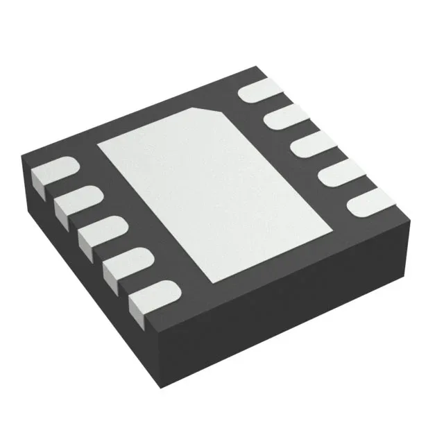
Texas Instruments TPS40190DRCR — Analog & Data Acquisition

TPS40190DRCR Buck Controller, 300kHz, 10-VSON

MPNTPS40190DRCR
End of Life

Texas Instruments TPS40190DRCR, step-down buck controller, 4.5V to 15V supply, 300kHz fixed switching frequency, 85% max duty cycle, synchronous rectifier, enable pin, single output, -40°C to 85°C, 10-VSON (3x3) exposed pad package.

$2.72Ref. price · indicative, final on quote
Packaging10-VFDFN Exposed Pad
RoHSROHS3 Compliant
Independent supplier — new & surplus stockAuthenticity-screened · ESD-safe packingListing updated Aug 2026

Specifications

TPS40190DRCR specifications
ParameterValue
Output typeTransistor Driver
MountingSurface Mount
Voltage - supply (Vcc (Vdd))4.5V ~ 15V
Frequency - switching300kHz
I/O channels1
Output phases1
Duty cycle85%
Operating temperature-40°C ~ 85°C (TA)
PackageTape & Reel (TR); Cut Tape (CT)
FunctionStep-Down
TopologyBuck
Clock syncNo
Case10-VFDFN Exposed Pad
Control featuresEnable
Output configurationPositive
Synchronous rectifierYes

Product details

Enable pin and control features

The TPS40190DRCR includes a dedicated enable pin for on/off control, allowing the controller to be sequenced with other rails or shut down under fault conditions. The enable threshold is referenced to the Vcc supply; pulling the pin below the threshold disables the output. There is no clock synchronization input — the oscillator runs free at 300 kHz, so multiple TPS40190DRCRs on the same board will beat against each other unless the switching nodes are phase-shifted with external RC delays or the layout separates the power stages.

Frequently asked questions

Does TPS40190DRCR have an enable pin?

Yes, the TPS40190DRCR includes an enable pin for on/off control. The enable threshold is referenced to Vcc; pulling the pin low disables the output.

What is the typical application circuit for TPS40190DRCR?

The TPS40190DRCR is a voltage-mode buck controller driving external N-channel MOSFETs in a synchronous rectifier topology. A typical circuit includes an input capacitor, the controller with its compensation network, a pair of MOSFETs, an output inductor, and output capacitors. The 300 kHz fixed switching frequency sets the LC filter values.

What is the closest functional second-source for TPS40190DRCR?

The UCC2806DWTR is a different part — it is a current-mode controller for boost, flyback, and forward topologies with two outputs and a 50% duty cycle limit. It is not a pin-compatible or functional replacement for the TPS40190DRCR buck controller. No direct second-source alternate is listed in the record for the TPS40190DRCR.