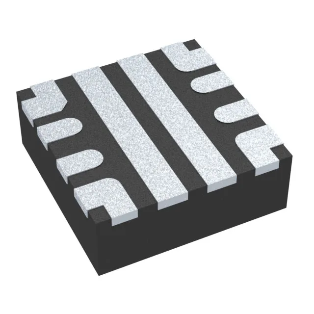
7 A electronic fuse in a 2×2 mm VQFN
The Texas Instruments TPS25974ARPWR is an integrated electronic fuse rated for a continuous 7 A output across a 2.7 V to 23 V input range. It replaces a discrete hot-swap controller plus sense resistor and MOSFET in a single 10-VQFN-HR package measuring just 2×2 mm. The ±10% current-limit accuracy sets the guard band you need to dimension the load — at 7 A nominal, the trip point could land anywhere from 6.3 A to 7.7 A, so the downstream rail and PCB trace must handle the high side without nuisance tripping. The junction temperature range of -40°C to 125°C suits industrial motor drives, base-station power feeds, and automotive body controllers where the ambient inside the enclosure can hit 85°C and the self-heating from 7 A adds another 30-40°C delta. The 2×2 mm footprint demands careful thermal via stitching under the exposed pad to pull heat into the inner copper planes — without it, the thermal shutdown will engage well below the current rating at elevated ambient.
Package and footprint — the 2×2 mm design constraint
The TPS25974ARPWR is supplied in a 10-VQFN-HR package (2×2 mm body). The HR suffix indicates a high-thermal-performance variant with an exposed pad. The pad is the main heat path; the datasheet layout recommends a 2.2×2.2 mm pad on the PCB with a 0.2 mm solder-mask opening per side, connected to the ground plane through at least nine thermal vias (0.3 mm diameter). The 10 leads are arranged on a 0.5 mm pitch — this is a QFN, so hand-soldering is possible with a hot-air station and flux, but reflow is preferred for consistent solder-joint quality.
The ROHS3 compliance covers all current EU and China RoHS exemptions. Tape & Reel (TR) is the standard delivery form; Cut Tape (CT) is also available for prototype or low-volume builds.
The ±10% accuracy figure applies to the current-limit threshold, not the input voltage or the pass-element RDS(on). If you set the limit resistor for 7 A, the actual trip point could be as low as 6.3 A or as high as 7.7 A over temperature and process. For a 7 A load that must never see a nuisance trip, you need to set the limit resistor to deliver a nominal 7.7 A and accept that the fuse will trip at 8.5 A worst-case — or oversize the PCB trace and connector to handle the higher ceiling. Conversely, if the downstream circuit cannot survive more than 7 A, set the limit to 6.3 A nominal and accept that it may trip at 5.7 A on a cold day.