What this dual high-side switch does for your rail
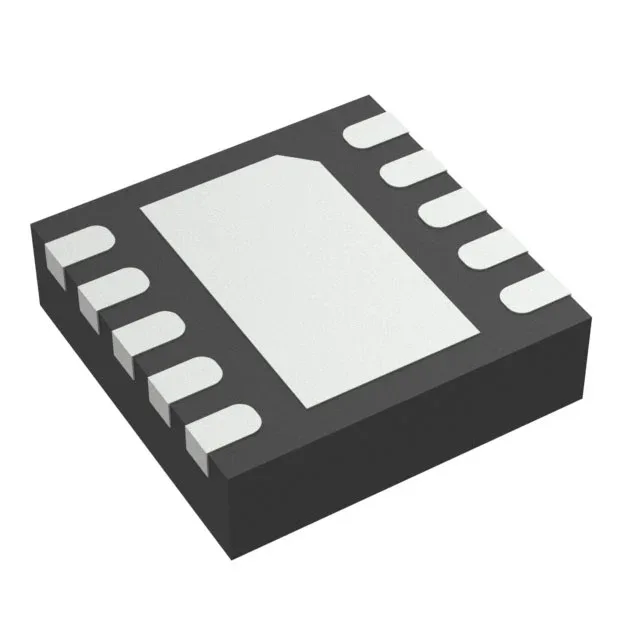
The TPS2560DRCR is a dual-channel, 1:2 high-side N-channel power switch from Texas Instruments, rated for a load voltage from 2.5 V to 6.5 V and delivering up to 2.5 A per channel. The typical on-resistance of 44 mOhm keeps conduction losses low enough that the 10-VSON (3x3 mm) exposed-pad package can dissipate the heat without forced airflow — a layout consideration for the thermal pad via pattern under the part. The switch is controlled by an On/Off interface with a non-inverting input, and it does not require a separate Vcc supply — the gate drive is derived from the load voltage. The integrated fault protection includes adjustable current limiting, over-temperature shutdown, and undervoltage lockout (UVLO), with a status flag output to signal the host controller when a fault condition is active.
Why the 44 mOhm Rds(on) and 2.5 A rating matter for your BOM
At 2.5 A output, the 44 mOhm typical Rds(on) produces a conduction loss of roughly 275 mW per channel. If your load is pulsed or you need headroom for derating at high ambient, the adjustable current limit lets you set the trip point below the 2.5 A maximum. The slew-rate controlled turn-on reduces inrush current into capacitive loads, which prevents upstream supply droop. The status flag output is an open-drain active-low signal that asserts during over-current or over-temperature events — useful for sequencing a downstream load or logging faults in a system controller.
For BOM planning: the part is single-sourced from TI, with no direct second-source on the market. If you are concerned about long-term availability, the adjustable current limit and fault-protection feature set are broadly covered by TI's TPS256x family, but pin compatibility across siblings should be verified against the datasheet footprint drawing. We can quote against your BOM quantity and confirm current lead time at quote time.